From Breaker to Breakers: A Guide to Electrical Protection


Electricity, the lifeblood of modern civilization, powers everything from the smallest household appliance to vast industrial complexes and critical infrastructure. Its omnipresence is so profound that we often take its steady supply for granted. Yet, beneath the surface of this convenience lies a potent force, capable of immense destruction and danger if not properly managed and contained. The very energy that illuminates our homes and drives our industries can, in an instant, become a source of fire, electrocution, or catastrophic equipment failure. This inherent duality necessitates an unwavering commitment to electrical protection – a sophisticated and continually evolving discipline dedicated to safeguarding lives, preventing property damage, and ensuring the uninterrupted, reliable operation of electrical systems.
The journey of electrical protection is a testament to human ingenuity, born from the earliest recognition of electricity's hazards and progressing through centuries of innovation. From the rudimentary fuse wire of the late 19th century to the intricate, intelligent protection schemes of today's smart grids, the fundamental goal has remained constant: to isolate faults quickly and effectively, minimizing harm and maximizing system resilience. This guide embarks on a detailed exploration of this vital field, tracing the evolution of protective devices, dissecting their underlying principles, examining their diverse applications, and peering into the future of safeguarding our electrified world. We will delve into the granular details of various protection technologies, from the ubiquitous miniature circuit breaker (MCB) in our homes to the advanced relays governing high-voltage transmission lines, shedding light on the critical role each plays in maintaining the delicate balance between power and safety. Understanding these mechanisms is not merely an academic exercise; it is an essential foundation for anyone involved in the design, installation, maintenance, or operation of electrical systems, ensuring that the power we harness serves us reliably and safely.
Chapter 1: The Fundamental Principles of Electrical Protection
Electrical protection is not a monolithic concept but rather a multifaceted engineering discipline built upon a bedrock of fundamental principles. At its core, it is about anticipating and mitigating the adverse effects of abnormal electrical conditions. These conditions, often termed "faults," can arise from a myriad of sources, including insulation failure, human error, environmental factors, or even the natural aging of equipment. Without adequate protection, a simple fault can quickly cascade into widespread outages, severe equipment damage, and, most critically, endanger human lives.
The primary objectives of any electrical protection system are threefold: 1. Safety to Personnel: This is paramount. Protection systems must quickly isolate faulty circuits to prevent electric shock, arc flash incidents, and fires that could injure or kill individuals. The rapid interruption of fault currents is essential to limit the exposure time to hazardous conditions. 2. Protection of Equipment: Electrical components and machinery are expensive assets. Sustained overcurrents, overvoltages, or short circuits can cause irreparable damage, leading to costly repairs, replacements, and significant downtime. Effective protection extends the lifespan of equipment by shielding it from such destructive forces. 3. Maintenance of System Stability and Reliability: In complex electrical networks, a fault in one section can destabilize the entire system, leading to widespread power outages. Protection systems are designed to localize faults, ensuring that only the affected section is isolated, thereby preserving power to healthy parts of the network and maintaining the overall stability and reliability of the supply. This also minimizes the restoration time after a fault.
To comprehend how protection systems achieve these objectives, a brief review of basic electrical concepts is necessary. * Voltage (V): The electrical potential difference that drives current through a circuit. Measured in Volts. * Current (I): The flow of electric charge. Measured in Amperes. * Resistance (R): The opposition to the flow of current. Measured in Ohms. * Power (P): The rate at which electrical energy is transferred. Calculated as P = V * I. Measured in Watts.
These quantities are interconnected by Ohm's Law (V = I * R), which is foundational to understanding fault conditions. When a fault occurs, the resistance in a circuit path can drop dramatically, leading to a massive surge in current.
Types of Electrical Faults
Understanding the different types of faults is crucial for designing effective protection schemes. Each fault type presents unique challenges and requires specific detection and interruption mechanisms.
- Overload: This occurs when a circuit draws more current than it is designed to safely handle, but less than a short circuit. It's often due to too many appliances operating simultaneously on a single circuit or a motor drawing excessive current under strenuous conditions. Overloads cause wires and components to overheat, leading to insulation degradation, fire hazards, and reduced equipment lifespan. They are characterized by a gradual increase in current above the rated capacity.
- Short Circuit: This is the most severe and dangerous type of fault. It happens when an unintended, low-resistance path is created for current to flow, bypassing the normal load. This can occur due to faulty wiring, damaged insulation, or direct contact between live conductors (phase-to-phase, phase-to-neutral, or phase-to-ground). Short circuits result in extremely high currents (often thousands of times the normal operating current), generating immense heat and electromagnetic forces that can cause explosions, arc flashes, and severe damage to conductors and equipment in milliseconds.
- Ground Fault (Earth Fault): A specific type of short circuit where current unintentionally flows from a live conductor to the ground or an earthed metallic object. This is particularly dangerous for humans, as touching an earthed object while a ground fault is present can complete the circuit through the body, leading to fatal electrocution. Ground faults are often difficult to detect with standard overcurrent protection alone, especially if the fault current is too low to trip a conventional circuit breaker but still high enough to be lethal.
- Arc Fault: An unintended arc created when electricity jumps across a gap between two conductors or between a conductor and ground. These arcs can be invisible and often occur in damaged wires, loose connections, or frayed appliance cords. Arc faults generate intense heat and can easily ignite surrounding combustible materials, leading to electrical fires. Unlike short circuits, arc faults often involve lower currents that may not be detected by traditional overcurrent devices but are nevertheless highly destructive.
- Overvoltage: Occurs when the voltage in a circuit exceeds its nominal design limits. This can be caused by lightning strikes (transient surges), switching operations in power systems, or faults in transformers and voltage regulators. Overvoltages can damage sensitive electronic components, degrade insulation, and lead to premature equipment failure.
Coordination and Selectivity
A cornerstone of effective electrical protection in complex systems is the concept of coordination (or discrimination) and selectivity. This principle dictates that when a fault occurs, only the protective device nearest to the fault should operate, isolating the smallest possible section of the network. All other upstream protective devices should remain closed, ensuring that the unaffected parts of the system continue to receive power.
Imagine a large industrial plant with multiple layers of protection: a main circuit breaker for the entire plant, sub-breakers for individual production lines, and further breakers for specific machines. If a fault occurs on a single machine, a perfectly coordinated system will ensure that only the machine's breaker trips. The production line continues to operate, and the rest of the plant remains energized. Without proper coordination, the fault on the single machine could trip the main plant breaker, shutting down the entire facility unnecessarily.
Achieving coordination involves careful selection and setting of protective devices based on their time-current characteristics, ensuring a hierarchy of operation. Devices closer to the load are set to trip faster or at lower current thresholds than those further upstream. This complex design process is critical for maintaining high levels of reliability and minimizing disruptions, forming a protective ecosystem where each component understands its precise role in safeguarding the larger network.
Chapter 2: The Evolution of Circuit Interruption Devices
The history of electrical protection is largely the history of devices designed to interrupt fault currents. From rudimentary beginnings to sophisticated modern apparatus, each innovation has contributed to greater safety, efficiency, and reliability.
Early Beginnings: Fuses
The fuse is arguably the oldest and simplest form of overcurrent protection, dating back to Thomas Edison's work in the late 19th century. Its operation is based on a fundamental principle: a thin metallic wire or strip designed to melt and break the circuit when current exceeds a predetermined safe level.
- How they work: The fuse element has a specific resistance. When current flows, it generates heat (I²R losses). If the current becomes excessive, the heat generated causes the fuse element to reach its melting point, physically breaking the circuit. This acts as a one-time sacrificial device.
- Types of Fuses:
- Cartridge Fuses: Cylindrical fuses with a metal cap at each end, encased in a ceramic or glass body, containing the fuse element. Common in both domestic and industrial applications for their reliability and wide range of current ratings.
- Plug Fuses: Typically found in older residential installations, these screw into a standard light bulb socket. They have a visible fuse element and are easily replaceable.
- Re-wireable Fuses (Rewirable Service Fuses): Primarily used in older, lower-voltage applications, these allowed the fuse wire to be replaced by hand. While cost-effective, they are less precise and carry a higher risk of incorrect wire replacement, making them less common in modern installations.
- Pros: Simplicity, reliability, cost-effectiveness, zero maintenance (once installed), and very high short-circuit interrupting capacity for many types.
- Cons: Non-reusable (must be replaced after tripping), cannot be reset, difficult to coordinate precisely with other protective devices in complex systems, and can cause single-phasing issues in three-phase systems if only one fuse blows.
Fuses remain a vital component in many protection schemes, particularly for their high breaking capacity in specific industrial and high-voltage applications where they offer superior fault current limitation compared to circuit breakers.
The Dawn of Breakers: Thermal-Magnetic Circuit Breakers
The invention of the circuit breaker marked a significant leap forward, introducing a reusable and more sophisticated method of protection. Unlike fuses, circuit breakers can be reset after tripping, making them more convenient and cost-effective in the long run.
- Thermal-Magnetic Circuit Breakers (MCBs & MCCBs): These are the workhorses of low-voltage electrical protection, combining two distinct tripping mechanisms:
- Thermal Trip (Overload Protection): A bimetallic strip inside the breaker heats up due to excessive current. As it heats, the two metals expand at different rates, causing the strip to bend. This bending mechanism trips a latch, opening the breaker contacts. This response is inverse-time, meaning the higher the overload current, the faster the strip heats and bends, and thus the faster the breaker trips. This accurately mimics the thermal characteristics of conductors.
- Magnetic Trip (Short Circuit Protection): A coil of wire (solenoid) is integrated into the current path. When a large fault current (like a short circuit) flows, it creates a strong electromagnetic field in the coil. This field instantaneously attracts an armature, which mechanically trips the latch, opening the contacts. The magnetic trip is instantaneous and operates at a much higher current threshold than the thermal trip, providing rapid protection against dangerous short circuits.
- Types:
- Miniature Circuit Breakers (MCBs): Commonly used in residential, commercial, and light industrial applications up to 125A. They are designed for branch circuit protection.
- Molded Case Circuit Breakers (MCCBs): Used in heavier commercial and industrial applications, ranging from 10A to 2500A. MCCBs offer adjustable trip settings, making them more versatile for coordinating with other devices in complex distribution systems. They provide a higher interrupting rating than MCBs.
- Trip Curves: A critical characteristic of circuit breakers is their time-current characteristic curve, which graphically depicts the time it takes for the breaker to trip at various fault currents. These curves are essential for proper coordination, allowing engineers to select breakers that will operate selectively.
Specialized Breakers: Enhancing Safety
As our understanding of electrical hazards deepened, specialized circuit breakers emerged to address specific, insidious dangers not adequately covered by thermal-magnetic protection.
- Ground Fault Circuit Interrupters (GFCIs) / Residual Current Devices (RCDs) / Residual Current Circuit Breakers (RCCBs):
- Principle: These devices are designed to protect against electric shock by detecting small imbalances in current. They operate on the principle that in a healthy circuit, the current flowing out on the "hot" (live) wire should be exactly equal to the current flowing back on the "neutral" wire. If there's a ground fault, some current will bypass the neutral wire and flow to the ground (e.g., through a person's body).
- A GFCI uses a current transformer (differential transformer) that continuously monitors the current in both the hot and neutral conductors. If an imbalance (typically 5mA to 30mA, depending on region and application) is detected, it indicates current leaking to ground, and the device trips almost instantaneously (within milliseconds), cutting off power.
- Importance: GFCIs are indispensable for human safety, especially in wet or outdoor locations where the risk of electric shock is elevated (e.g., bathrooms, kitchens, swimming pool areas, construction sites). They provide protection against ground faults that may not draw enough current to trip a standard thermal-magnetic breaker but are still lethal.
- Arc Fault Circuit Interrupters (AFCIs):
- Principle: Unlike GFCIs which detect current imbalances, AFCIs are engineered to identify the unique signatures of dangerous electrical arcs (sparking) that can lead to fires. They use sophisticated electronic circuitry and digital signal processing to analyze the current waveform for patterns characteristic of various arc faults (e.g., series arcs, parallel arcs, ground arcs).
- Importance: AFCIs are specifically designed to prevent electrical fires caused by faulty wiring, damaged insulation, or loose connections. These arc faults often involve currents below the trip threshold of conventional breakers, making AFCIs a crucial line of defense in protecting homes and buildings from fire hazards. They are increasingly mandated in residential circuits, particularly in bedrooms and living areas.
- Earth Leakage Circuit Breakers (ELCBs):
- Principle: ELCBs are an older type of ground fault protection that operates by detecting a voltage difference between the protected circuit and a local ground electrode. If the voltage difference exceeds a certain threshold, the ELCB trips.
- Evolution: While effective, ELCBs are largely superseded by RCDs/GFCIs (which are current-operated) because ELCBs require a separate, reliable connection to an earthing electrode, and their effectiveness can be compromised if this connection is poor. Current-operated RCDs/GFCIs are generally considered more reliable as they do not depend on the quality of a separate earthing connection.
Industrial and High-Voltage Breakers
As power systems grew in scale and complexity, the demands on circuit breakers intensified, leading to the development of specialized breakers for high-current and high-voltage applications. These devices must interrupt fault currents of immense magnitude, often in the hundreds of kiloamperes, while withstanding very high recovery voltages.
- Air Circuit Breakers (ACBs):
- Principle: Used in low-voltage main distribution panels (up to 690V, thousands of amps), ACBs use air as the arc quenching medium. When contacts open, an arc forms between them. This arc is drawn into arc chutes, where it is elongated, cooled, and split into smaller, more manageable arcs, eventually extinguishing it.
- Applications: Main incoming protection, bus coupler protection, and large motor feeder protection in industrial plants and commercial buildings. They often feature highly adjustable electronic trip units for precise coordination.
- Vacuum Circuit Breakers (VCBs):
- Principle: Employed in medium-voltage applications (typically 1kV to 38kV), VCBs interrupt current in a sealed vacuum interrupter. When contacts separate in a vacuum, the arc produced is rapidly diffused and extinguished because there are no air molecules to ionize and sustain it.
- Advantages: Compact size, long electrical life, minimal maintenance, environmentally friendly (no SF6 gas), and quiet operation.
- Applications: Power distribution systems, industrial switchgear, motor control centers, and utility substations.
- SF6 Circuit Breakers (Sulfur Hexafluoride Circuit Breakers):
- Principle: Predominantly used in high-voltage and extra-high-voltage transmission systems (from 33kV up to 800kV), SF6 gas is an excellent arc-quenching and insulating medium. When contacts separate, SF6 gas is blown across the arc, rapidly cooling it and extinguishing it.
- Advantages: Extremely high interrupting capacity, excellent dielectric strength (insulating properties), compact design for very high voltages, and rapid arc extinction.
- Concerns: SF6 is a potent greenhouse gas, necessitating careful handling and leak prevention. Research into environmentally friendly alternatives is ongoing.
- Applications: Major power transmission substations, grid interconnections, and large industrial facilities.
Each type of circuit breaker, from the humble MCB to the massive SF6 breaker, represents a carefully engineered solution to a specific set of protection challenges, collectively forming a robust defense against the inherent dangers of electricity.
Chapter 3: Beyond Basic Breakers: Advanced Protection Relays and Systems
While circuit breakers are the ultimate actuators of protection, actually interrupting the fault current, they often rely on sophisticated "brains" to decide when and where to trip. These brains are protective relays, devices that detect abnormal conditions and initiate the tripping of a circuit breaker. The evolution of relays mirrors the advancements in electronics and computing, moving from crude mechanical devices to highly intelligent digital processors.
Protective Relays
- Historical Context: Electromechanical Relays:
- The earliest protective relays were electromechanical. They consisted of coils, magnets, springs, and levers. When fault current flowed through a current transformer connected to the relay, it energized a coil, creating a magnetic field that moved an armature or disk. This movement, against a spring force, operated a contact that then tripped a circuit breaker.
- Types: Overcurrent relays (induction disc), differential relays, distance relays.
- Pros: Simple, robust, immune to electromagnetic interference (EMI).
- Cons: Bulky, slow response times, fixed characteristics, required frequent calibration, limited functionality, difficult to coordinate.
- Modern Relays: Microprocessor-Based (Digital/Numerical) Relays:
- The advent of microprocessors revolutionized relay technology. Modern relays are essentially specialized computers. They sample analog current and voltage waveforms, convert them to digital signals, and then apply complex algorithms to detect faults.
- Enhanced Functionality: Digital relays can incorporate dozens of protection functions (e.g., multiple stages of overcurrent, ground fault, overvoltage, undervoltage, frequency, differential, distance, power directional, etc.) within a single device.
- Programmability: Settings can be precisely adjusted via software, allowing for highly flexible and adaptive protection schemes. This includes multiple setting groups to adapt to changing system configurations (e.g., different load conditions or network topologies).
- Communication Capabilities: Modern relays are equipped with communication ports (Ethernet, serial) and support various protocols (e.g., IEC 61850, Modbus, DNP3). This allows them to communicate with each other, with SCADA systems, and with other control and monitoring platforms, enabling advanced functions like remote control, data logging, and event reporting.
- Self-Diagnosis and Monitoring: They can continuously monitor their own health and report any internal issues. They also log fault events with high precision (time-stamped waveforms, sequence of events), invaluable for post-fault analysis.
- Pros: Compact, fast, highly accurate, versatile, self-monitoring, excellent for coordination, extensive data logging, and remote accessibility.
- Cons: More complex to configure, susceptible to cyber threats (if not secured), and require specialized software and expertise.
Types of Protection Functions and Their Applications
Digital relays can implement a wide array of protection functions, each designed for specific fault types and system components:
- Overcurrent Protection (50/51): Detects excessive current.
- Instantaneous Overcurrent (50): Trips immediately when current exceeds a very high, preset value (e.g., short circuits).
- Inverse Definite Minimum Time (IDMT) Overcurrent (51): Trips after a time delay that is inversely proportional to the current magnitude (higher current, shorter time). Essential for coordination.
- Differential Protection (87): Highly sensitive and fast protection for critical equipment like transformers, generators, and busbars. It compares the current entering a protected zone with the current leaving it. In a healthy system, these currents should be equal. Any significant difference indicates an internal fault within the zone, triggering a trip.
- Distance Protection (21): Primarily used for transmission and long distribution lines. It measures the impedance (voltage divided by current) seen from the relay location. Since impedance is proportional to distance along the line, a low impedance indicates a fault close to the relay, and a higher impedance indicates a fault further away. Distance relays provide high-speed primary protection for a defined zone and backup protection for adjacent zones.
- Overvoltage/Undervoltage Protection (59/27): Detects abnormal voltage levels that can damage equipment or indicate system instability.
- Frequency Protection (81): Monitors system frequency, crucial for grid stability, especially during generation-load imbalances.
Relay Coordination
As mentioned earlier, coordination is paramount. With modern relays, this involves creating a comprehensive coordination study that analyzes all possible fault scenarios and meticulously sets the trip characteristics (current thresholds, time delays, operating curves) of every relay and circuit breaker in the system. The goal is a perfectly hierarchical tripping sequence, minimizing system disruption. This study involves:
- Plotting Time-Current Curves: Graphically representing the operating characteristics of all protection devices on a single log-log plot to ensure proper gaps between curves for selective tripping.
- Fault Current Calculations: Determining the maximum and minimum fault currents at various points in the system to verify that protection devices can detect and interrupt them.
- Sequential Operation: Ensuring that the device closest to the fault operates first, followed by upstream devices with progressively longer time delays, providing backup protection.
Substation Protection
Substations are critical nodes in the power grid, transforming voltages and distributing power. Their protection systems are among the most complex, encompassing a layered approach to safeguard multiple components:
- Transformer Protection: Differential protection (87T) is primary, augmented by overcurrent (51), sudden pressure, and temperature monitoring.
- Busbar Protection: High-speed differential protection (87B) is crucial here, as a fault on a busbar can disrupt power to multiple feeders. Often uses low-impedance or high-impedance differential schemes.
- Line Protection: Distance relays (21) for transmission lines, and overcurrent (50/51) or recloser controls for distribution lines. Auto-reclosing functionality is common to automatically attempt to restore power after transient faults.
- Generator Protection: Highly intricate, involving protection against overcurrent, overvoltage, undervoltage, negative sequence currents, loss of excitation, reverse power, and differential faults.
Surge Protection Devices (SPDs)
Beyond fault currents, electrical systems are also vulnerable to transient overvoltages, or surges, which can arise from lightning strikes, switching operations (e.g., disconnecting inductive loads), or even electrostatic discharge. These surges, though often very brief, can carry enormous energy and cause significant damage to sensitive electronic equipment.
Surge Protection Devices (SPDs) are designed to divert these transient overvoltages to ground, protecting downstream equipment.
- How they work: SPDs typically contain components like Metal Oxide Varistors (MOVs) or gas discharge tubes. These components have a very high impedance under normal operating voltage but rapidly switch to a very low impedance when an overvoltage surge occurs. This effectively "shunts" the surge current away from the protected equipment and safely to earth, clamping the voltage at a safe level. Once the surge passes, the SPD reverts to its high-impedance state, allowing normal operation.
- Classes of SPDs: SPDs are often categorized into types based on their location and protection capability:
- Type 1 SPDs: Installed at the main service entrance (e.g., utility transformer or main switchboard) to protect against high-energy surges from external sources like lightning.
- Type 2 SPDs: Installed at sub-distribution boards or directly at the equipment to protect against residual surges and internally generated surges.
- Type 3 SPDs: Point-of-use protection, often integrated into power strips or directly into equipment, for sensitive electronics.
- Importance: With the proliferation of sensitive microelectronics in homes and industries, SPDs are increasingly vital. They not only prevent immediate damage but also extend the lifespan of equipment by mitigating the cumulative effects of smaller, repetitive surges.
Together, advanced protection relays and SPDs form an intelligent and robust shield, ensuring the resilience and longevity of electrical infrastructure against both sustained faults and fleeting, powerful transients.
APIPark is a high-performance AI gateway that allows you to securely access the most comprehensive LLM APIs globally on the APIPark platform, including OpenAI, Anthropic, Mistral, Llama2, Google Gemini, and more.Try APIPark now! 👇👇👇
Chapter 4: System Integration and Smart Grids
The modern electrical grid is a marvel of engineering, but it is also undergoing a profound transformation. Moving from a unidirectional, centralized power delivery model to a complex, bidirectional, and decentralized "smart grid" necessitates an unprecedented level of system integration, data exchange, and intelligent management. This evolution profoundly impacts how electrical protection is designed, implemented, and managed.
SCADA and DMS: The Nervous System of the Grid
At the heart of modern grid operations are sophisticated control and monitoring systems:
- SCADA (Supervisory Control and Data Acquisition): This system collects real-time data from various field devices (sensors, meters, protection relays, circuit breakers) across wide geographical areas. It provides operators with a comprehensive view of the grid's status, allowing them to monitor conditions, identify problems, and issue remote commands (e.g., opening/closing breakers, adjusting setpoints). In the context of protection, SCADA allows operators to see which breakers have tripped, analyze event logs from relays, and initiate remote reclosure attempts or fault isolation procedures. It aggregates crucial data for effective decision-making.
- DMS (Distribution Management Systems): DMS are specialized SCADA systems focused on the distribution network. They provide advanced applications for optimizing distribution operations, including:
- Fault Location, Isolation, and Service Restoration (FLISR): Automatically identifies fault locations, isolates the faulted section by operating remote-controlled switches or reclosers, and then restores power to unfaulted sections by reconfiguring the network. This significantly reduces outage times.
- Voltage/VAR Optimization: Manages voltage levels and reactive power flow for efficiency.
- Load Management: Optimizes power delivery to consumers.
- DMS heavily relies on the data and control capabilities provided by intelligent protection devices and communication networks.
Smart Grid Architectures: Interconnectedness and Real-Time Monitoring
The "smart grid" concept integrates advanced communication technologies, sensors, and intelligent control systems into the traditional electricity network. Its key characteristics include:
- Bidirectional Power Flow: Accommodating distributed generation (e.g., rooftop solar, wind farms) where consumers can also become producers. This introduces new challenges for protection, as fault currents can flow in multiple directions.
- Real-time Monitoring and Control: Extensive deployment of Intelligent Electronic Devices (IEDs) – including modern protective relays – provides granular data on grid conditions (current, voltage, frequency, power quality) in real-time.
- Self-Healing Capabilities: The ability to automatically detect, isolate, and restore power after faults, minimizing human intervention and outage durations.
- Enhanced Cybersecurity: Protecting critical infrastructure from digital attacks.
The Role of Communication Protocols
Effective smart grid operation and advanced protection rely heavily on robust and standardized communication protocols that enable diverse devices to "speak" to each other.
- IEC 61850: This international standard defines communication networks and systems for power utility automation. It's a comprehensive framework that specifies data models, communication services, and logical nodes for intelligent electronic devices (IEDs) in substations. IEC 61850 enables seamless interoperability between relays from different manufacturers, facilitating advanced protection schemes (e.g., peer-to-peer tripping, station-wide interlocking) and high-speed data exchange. Its Generic Object Oriented Substation Event (GOOSE) messages allow protective relays to communicate critical trip signals directly and extremely quickly, crucial for high-speed differential and busbar protection.
- Modbus and DNP3: Older but still widely used protocols, especially in SCADA systems. Modbus is simpler, often used for device-level communication. DNP3 (Distributed Network Protocol 3) is more robust, designed for master-slave communication in utility environments, offering enhanced security and data integrity features. These protocols are essential for data acquisition from legacy devices and for remote control.
Managing the Information Flow: The Role of AI Gateways and API Management
The increasing complexity and interconnectedness of smart grids generate an immense volume of data from various sources: smart meters, protective relays, sensors, distributed energy resources, weather stations, and market systems. This data, often disparate in format and protocol, needs to be efficiently collected, processed, and securely exchanged between different applications, platforms, and stakeholders (utilities, third-party service providers, consumers). This is where sophisticated data management and integration solutions become crucial.
In this environment, an API Gateway acts as a central entry point for managing, securing, and routing API requests to various backend services. For a smart grid, this could mean:
- Standardizing Access: Providing a unified interface for applications to access data from different grid components, regardless of their underlying protocols (e.g., exposing IEC 61850 data as REST APIs).
- Security: Enforcing authentication, authorization, and encryption policies for all API traffic, protecting critical grid data and control functions from unauthorized access.
- Traffic Management: Handling routing, load balancing, caching, and rate limiting for API calls, ensuring system stability and performance under heavy loads.
- Monitoring and Analytics: Logging all API interactions, providing insights into data consumption, potential anomalies, and system health.
Consider a scenario where a utility wants to integrate data from its protective relays with a predictive maintenance platform, an asset management system, and an outage management system. Each of these platforms might require data in different formats or communicate using different protocols. An API Gateway simplifies this by:
- Exposing Relay Data: The gateway can expose real-time and historical data from protective relays (e.g., trip counts, fault waveforms, operational status) as standardized APIs.
- Facilitating Integration: The predictive maintenance platform can then call these APIs to gather data for analysis, identifying patterns that might indicate impending equipment failure. The asset management system can update equipment health records, and the outage management system can receive instant alerts.
- Advanced Analytics with AI: Furthermore, with the rise of artificial intelligence in grid operations (e.g., for fault prediction, demand forecasting, optimal resource dispatch), an AI Gateway becomes indispensable. This specialized gateway manages access to a variety of AI models, ensuring consistent invocation, authentication, and cost tracking. For instance, a utility might use an AI model (perhaps even one leveraging a Large Language Model (LLM) Gateway for sophisticated textual analysis of maintenance reports or operational logs, though this is a more cutting-edge application) to analyze massive datasets from protection devices and sensors to predict when a transformer might fail or when a particular feeder is likely to experience an overload.
This is precisely where an open-source platform like APIPark demonstrates its value. As an all-in-one AI gateway and API developer portal, APIPark can serve as the connective tissue for these complex smart grid integrations. It allows utilities to quickly integrate data from various grid components, standardizing the API format for invocation, enabling consistent management of authentication and cost tracking for API calls, and even encapsulating custom prompts with AI models to create new analytical APIs (e.g., a "fault diagnosis API" that uses an integrated AI model). By providing end-to-end API lifecycle management, APIPark helps regulate API management processes, manage traffic forwarding, and ensures secure, authorized access to critical grid data and services. Its ability to support high transaction volumes (over 20,000 TPS) makes it suitable for the demanding performance requirements of modern utility infrastructure, and its detailed API call logging provides crucial audit trails and troubleshooting capabilities. In an increasingly data-driven and AI-enabled grid, platforms like APIPark are essential for managing the secure and efficient flow of information, underpinning advanced protection, monitoring, and operational intelligence.
Chapter 5: Installation, Maintenance, and Testing of Protection Systems
The most advanced protection devices are only as effective as their installation, maintenance, and testing regimes. A poorly installed or neglected system can fail to operate when needed, or worse, operate incorrectly, leading to devastating consequences. This chapter delves into the practical aspects of ensuring protection systems perform their crucial role reliably throughout their operational life.
Design Considerations
The life cycle of an electrical protection system begins long before any equipment is installed, with meticulous design and planning. This phase is paramount for ensuring effective and reliable operation.
- Fault Current Analysis: This is a foundational step. Engineers must accurately calculate the maximum and minimum fault currents that can occur at various points in the electrical network.
- Maximum Fault Current: Determines the required interrupting rating of circuit breakers and the short-time withstand capability of other equipment. Without this, a breaker might fail to interrupt a severe short circuit, leading to catastrophic equipment failure.
- Minimum Fault Current: Ensures that protection devices can detect the smallest fault currents (e.g., distant ground faults) that could still cause damage or pose a safety risk.
- Sophisticated software tools are used for these calculations, considering factors like utility source impedance, cable lengths, transformer impedances, and motor contributions.
- Protection Device Selection: Based on the fault current analysis and the specific application (e.g., motor feeder, transformer, transmission line), appropriate protection devices are selected. This involves choosing devices with:
- Correct Voltage and Current Ratings: Must match or exceed the system's nominal voltage and current.
- Adequate Interrupting Rating (AIC/kA): Must be able to safely interrupt the maximum prospective fault current at their location.
- Specific Protection Functions: E.g., overcurrent, ground fault, differential, arc fault, etc.
- Environmental Suitability: Resistance to dust, moisture, temperature extremes.
- Coordination Studies: This is where the selective tripping principle is put into practice. A detailed coordination study involves:
- Developing Time-Current Curves: Plotting the operating characteristics of all upstream and downstream protection devices on a single log-log graph.
- Ensuring Selectivity Gaps: Adjusting the settings (pickup currents, time delays) of relays and circuit breakers to create clear gaps between the curves, ensuring that the closest device to a fault trips first, with adequate time delay for backup devices.
- Consideration of Inrush Currents: Account for temporary high currents from motor starting or transformer energization to ensure protection devices don't trip unnecessarily during normal operations.
- Arc-Flash Studies: Increasingly integrated into coordination studies to assess potential arc-flash hazards, determine incident energy levels, and define appropriate PPE.
Installation Best Practices
Even the best-designed system can be compromised by poor installation. Adherence to industry standards and best practices is crucial.
- Wiring and Termination:
- Proper Conductor Sizing: Use conductors sized according to code (e.g., NEC, IEC) and the expected load, with adequate allowance for voltage drop and future expansion.
- Secure Terminations: Loose connections are a major cause of overheating, arcing, and intermittent faults. All connections must be tight, using appropriate tools and torque values.
- Segregation and Shielding: Control wiring for protection relays should be segregated from power cables to prevent electromagnetic interference (EMI). Shielded cables and proper grounding of shields are essential for sensitive digital relays.
- Clearly Labeled Wiring: All wires must be clearly labeled at both ends for ease of troubleshooting and maintenance.
- Grounding and Bonding:
- Effective Grounding System: A low-resistance path to earth for fault currents is critical for personnel safety and proper operation of ground fault protection devices.
- Equipotential Bonding: All non-current-carrying metallic parts of equipment and enclosures must be bonded together and connected to the grounding electrode system to ensure they are at the same electrical potential, preventing hazardous touch voltages during a fault.
- Separate Control Grounding: For digital relays, a clean, isolated ground reference is often required for reliable operation of sensitive electronics.
- Panel and Device Mounting:
- Proper Enclosure Selection: Use enclosures with appropriate NEMA or IP ratings for the environmental conditions (dust, water ingress).
- Adequate Space: Ensure sufficient working space around protective devices for safe operation, maintenance, and ventilation.
- Clear Labeling: All circuit breakers, fuses, and relays must be clearly labeled, identifying the circuit or equipment they protect. This is vital for quick identification during an emergency.
Regular Maintenance
Electrical protection systems, like any complex machinery, require ongoing maintenance to ensure their continued reliability. A proactive maintenance strategy is far more cost-effective than reactive repairs after a failure.
- Importance: Prevents premature failures, extends equipment lifespan, ensures compliance with safety regulations, and maintains system reliability. A protection system that fails to operate during a fault is worse than no system at all, as it creates a false sense of security.
- Types of Maintenance:
- Preventive Maintenance (PM): Scheduled inspections and servicing based on time intervals or usage.
- Visual Inspections: Check for signs of overheating (discoloration, melting), loose connections, dust accumulation, corrosion, physical damage, and proper indicator lights.
- Cleaning: Remove dust and debris from contacts and operating mechanisms.
- Lubrication: For mechanical components of larger breakers.
- Torquing: Re-tighten electrical connections.
- Predictive Maintenance (PdM): Uses condition monitoring techniques to predict potential failures before they occur.
- Thermal Imaging (Infrared Thermography): Detects hot spots indicating loose connections, overloaded circuits, or impending component failures.
- Vibration Analysis: For rotating equipment associated with breakers.
- Oil Analysis: For oil-filled transformers and breakers.
- Partial Discharge Testing: Detects insulation degradation in high-voltage equipment.
- Preventive Maintenance (PM): Scheduled inspections and servicing based on time intervals or usage.
- Inspection Checklists: Standardized checklists ensure that all critical components are inspected thoroughly. This includes checking trip units, auxiliary contacts, control wiring, spring charging mechanisms, and indicator flags.
Testing Procedures
Regular testing is the only way to verify that protection devices will operate correctly and within their specified parameters when a fault occurs. Testing intervals are typically governed by industry standards, manufacturer recommendations, and criticality of the equipment.
- Primary Injection Testing:
- Principle: Involves injecting a high current (up to several thousand amps) directly through the primary circuit of a circuit breaker or current transformer. This simulates an actual fault condition.
- Purpose: Verifies the complete protective path, including current transformers, wiring, and the breaker's trip unit. It confirms that the breaker trips at the correct current and within the correct time. Essential for commissioning and periodic verification of larger breakers and systems.
- Secondary Injection Testing:
- Principle: Involves injecting test currents and voltages directly into the secondary terminals of protective relays, simulating the inputs they would receive from current and voltage transformers during a fault.
- Purpose: Primarily tests the relay's internal logic, trip characteristics, and communication functions. It's used to verify relay settings, trip curves, and time delays without energizing the main power circuit. This is a common and safe method for testing digital relays.
- Relay Testing:
- Static/Dynamic Testing: Verifies the relay's response to various fault conditions, including overcurrent, voltage, frequency, differential, and distance functions.
- End-to-End Testing: For complex line protection schemes, communication-assisted protection, and reclosers, end-to-end testing verifies the entire protection chain, including communication links between relays at different ends of a line.
- Insulation Resistance Testing (Megger Testing):
- Principle: Applies a high DC voltage across insulation (e.g., between conductors and ground, or between phases) and measures the resulting leakage current. The resistance value indicates the health of the insulation.
- Purpose: Identifies degradation in cable insulation, transformer windings, motor windings, and switchgear, which could lead to short circuits or ground faults.
- Circuit Breaker Contact Resistance Testing:
- Principle: Measures the resistance across the main contacts of a closed circuit breaker.
- Purpose: High contact resistance indicates wear, pitting, or contamination, which can lead to overheating and potential failure to carry rated current or interrupt fault current effectively.
Safety Protocols: Lockout/Tagout (LOTO)
All maintenance and testing activities on electrical equipment must be performed under strict safety protocols. Lockout/Tagout (LOTO) is a critical procedure designed to prevent accidental energization of machinery or equipment during maintenance or servicing.
- Procedure: Involves physically isolating equipment from all energy sources (electrical, mechanical, hydraulic, pneumatic) and then placing a lock and a tag on the isolating device (e.g., circuit breaker, disconnect switch). The lock prevents unauthorized re-energization, and the tag provides information about who locked out the equipment and why.
- Importance: LOTO protects workers from unexpected startup of machinery, accidental release of stored energy, and exposure to live electrical conductors. Strict adherence to LOTO procedures is non-negotiable for anyone working on or near electrical systems.
The meticulous execution of these design, installation, maintenance, and testing practices is what truly underpins the reliability and safety of any electrical protection system. It transforms theoretical safeguards into tangible, operational defenses against the inherent risks of electricity.
Chapter 6: Modern Challenges and Future Trends in Electrical Protection
The electrical landscape is dynamic, constantly evolving with new technologies, energy sources, and societal demands. This evolution presents both unprecedented challenges and exciting opportunities for electrical protection, pushing the boundaries of traditional methods and fostering innovation towards a more resilient, intelligent, and sustainable grid.
Renewable Energy Integration
The global push towards decarbonization has led to a massive integration of renewable energy sources (RES) like solar photovoltaics (PV) and wind turbines. While environmentally beneficial, their integration presents significant challenges for traditional protection schemes:
- Bidirectional Power Flow: Conventional grids were designed for unidirectional power flow from central generation to consumers. RES, especially distributed generation (DG) at the distribution level, introduce bidirectional flow. This means fault currents can come from multiple directions, complicating traditional overcurrent relay settings and coordination. A fault downstream might now be fed by both the utility grid and local DG, requiring more sophisticated protection logic.
- Microgrids: These localized grids can operate connected to the main grid or in "island mode" when disconnected. Protecting microgrids requires adaptable protection schemes that can reconfigure settings rapidly based on operating mode. Islanding detection and protection for loads within the microgrid are critical.
- Inverter-Based Generation: Many RES (solar PV, battery storage) use inverters to convert DC to AC. Unlike synchronous generators that contribute large short-circuit currents during faults, inverters have limited fault current capabilities (typically 1.1 to 2 times rated current). This "low fault current" issue makes it challenging for traditional overcurrent relays to detect faults, especially ground faults, requiring new techniques like impedance-based protection or sensitive differential schemes.
- Grid Stability Challenges: The variability of renewables and the reduction of synchronous generator inertia can impact grid stability (frequency and voltage). Protection systems must be agile enough to respond to these dynamic changes without false tripping.
Cybersecurity for Protection Systems
As protection systems become more intelligent, interconnected, and reliant on digital communication, they also become potential targets for cyberattacks. A successful cyberattack on critical protection infrastructure could lead to:
- Widespread Power Outages: Maliciously operating breakers or disabling relays could cause cascading failures.
- Equipment Damage: Disabling protection could leave equipment vulnerable to fault currents.
- Physical Harm: Disabling safety interlocks or protective functions could endanger personnel.
Challenges and Solutions: * Vulnerability: Legacy systems were often air-gapped, but modern IEDs and SCADA systems are networked, increasing attack surface. * Secure Communication: Implementing robust encryption (e.g., VPNs, TLS), authentication (e.g., mutual authentication for IEC 61850 GOOSE messages), and secure protocols is crucial. * Intrusion Detection/Prevention Systems (IDPS): Monitoring network traffic for anomalous behavior indicative of attacks. * Segmentation: Isolating critical control networks from enterprise networks to limit lateral movement of attackers. * Access Control: Strict role-based access control and strong authentication for all operators and systems. * Regular Audits and Updates: Proactively identifying and patching vulnerabilities.
Artificial Intelligence and Machine Learning
AI and ML are poised to revolutionize electrical protection, offering capabilities far beyond traditional rule-based systems.
- Predictive Maintenance: AI algorithms can analyze vast amounts of operational data from protective relays, sensors, and asset management systems (e.g., temperatures, vibration, fault records, API call logs from systems like APIPark that manage data from grid components) to identify subtle patterns that precede equipment failure. This allows for proactive maintenance, preventing outages before they occur.
- Adaptive Protection: Instead of fixed settings, AI-driven protection systems can dynamically adjust their settings in real-time based on changes in grid topology, load conditions, or the presence of distributed generation. This optimizes coordination and ensures optimal protection under all operating scenarios.
- Enhanced Fault Location: ML models can rapidly and accurately pinpoint fault locations, even in complex or meshed networks, by analyzing voltage and current waveforms from multiple points. This significantly reduces restoration times.
- Anomaly Detection: AI can detect unusual behavior that may indicate incipient faults, cyberattacks, or equipment degradation that traditional thresholds might miss.
- Self-Healing Grids: AI can enable autonomous decision-making for fault detection, isolation, and service restoration, leading to truly self-healing capabilities in the grid, minimizing human intervention and outage durations. The complex data management required for these AI models to interact with grid components can be facilitated by robust AI Gateway solutions, streamlining the deployment and management of these intelligent analytics.
Advanced Sensing Technologies
Better data leads to better protection. Innovations in sensing are providing more precise and comprehensive insights into grid conditions.
- Non-Intrusive Sensors: Current sensors that don't require breaking the circuit, providing safer and easier installation.
- Fiber Optic Sensors: Immune to electromagnetic interference, they can be deployed over long distances (e.g., along transmission lines) to monitor temperature, strain, and even acoustic signatures indicative of faults, providing real-time distributed sensing capabilities.
- Phasor Measurement Units (PMUs): Provide synchronized voltage and current phasor measurements from widely dispersed locations with high precision. This "synchrophasor" data is crucial for wide-area monitoring, control, and protection, allowing real-time assessment of grid stability and rapid detection of oscillations or power swings.
Self-Healing Grids
This is the ultimate goal of smart grid development and represents the pinnacle of advanced protection. A self-healing grid can:
- Automatically Detect Faults: Using advanced protection relays and sensors.
- Isolate Faults: Operating remote-controlled switches and breakers to contain the problem to the smallest possible section.
- Reconfigure the Network: Intelligently rerouting power to bypass the faulted section, restoring service to healthy areas without human intervention.
- Restore Power: Once the fault is cleared, automatically bringing the isolated section back online.
This capability significantly improves reliability and customer satisfaction, particularly in areas prone to frequent outages.
Standardization and Regulations
The rapid evolution of electrical protection necessitates continuous updates to industry standards, codes, and regulations (e.g., IEEE, IEC, NEC, NERC). These standards provide frameworks for:
- Safety Requirements: Ensuring minimum safety levels for equipment and installations.
- Interoperability: Facilitating seamless communication and operation between diverse equipment from different manufacturers.
- Performance Benchmarks: Defining expected performance levels for protection devices.
- Cybersecurity Guidelines: Establishing best practices for securing critical infrastructure.
As the grid becomes more complex and integrated, these standards play a crucial role in ensuring consistency, safety, and reliability across the entire electrical ecosystem. The journey from the earliest fuse to the sophisticated, AI-driven protection systems of the future is a testament to the ongoing commitment to safeguarding our electrified world.
Conclusion
The evolution of electrical protection, aptly traced "From Breaker to Breakers," is a compelling narrative of human ingenuity driven by a fundamental imperative: to tame the potent force of electricity for progress while rigorously safeguarding against its inherent dangers. From the humble, single-use fuse to the intricate, microprocessor-based relays and the visionary concepts of self-healing smart grids, each advancement has been a step forward in enhancing safety, extending equipment lifespan, and bolstering the reliability of our critical electrical infrastructure.
We have explored the foundational principles that underpin every protective action, understanding why the rapid detection and isolation of faults are non-negotiable for protecting both human life and costly assets. The journey through the diverse array of circuit interruption devices, from the steadfast thermal-magnetic breakers to the life-saving GFCIs and fire-preventing AFCIs, highlights the specialized solutions developed for specific hazards. Beyond these primary actuators, we delved into the intelligence layer: the sophisticated protective relays that act as the watchful eyes and analytical brains of the system, making precise decisions in milliseconds to avert catastrophe.
The advent of the smart grid has introduced an era of unprecedented interconnectedness, where communication protocols like IEC 61850 and advanced control systems like SCADA and DMS transform raw data into actionable intelligence. In this complex, data-rich environment, the effective management of information flow through robust API Gateways, such as APIPark, becomes not just an advantage but a necessity. By standardizing access to diverse grid data, enabling secure communication, and facilitating the integration of advanced analytics and AI models for predictive maintenance and fault diagnosis, platforms like APIPark play a quiet yet crucial role in ensuring the operational efficiency and cybersecurity of modern electrical protection systems.
Finally, we looked at the critical practicalities of installation, meticulous maintenance, and rigorous testing – the unseen labor that ensures these intricate systems perform flawlessly when their moment of truth arrives. The challenges posed by renewable energy integration, the looming threat of cyberattacks, and the promise of artificial intelligence continue to shape the future of electrical protection. These forces are driving innovation towards more adaptive, intelligent, and resilient grids capable of anticipating threats, healing themselves, and ultimately providing even safer and more reliable power to a world ever more reliant on electricity.
The commitment to electrical protection is an ongoing endeavor, a continuous pursuit of perfection in a world where the stakes are nothing less than human safety and societal progress. As our reliance on electricity deepens, so too must our dedication to mastering its protection, ensuring that the power we harness serves us reliably and safely, now and for generations to come.
Frequently Asked Questions (FAQs)
- What is the fundamental difference between a fuse and a circuit breaker? A fuse is a single-use protective device that melts and breaks the circuit when an overcurrent occurs, requiring replacement after each operation. A circuit breaker, on the other hand, is a reusable device that trips (opens) during an overcurrent or fault condition and can be reset (closed) manually or automatically after the fault is cleared, making it more convenient and cost-effective in the long run. Circuit breakers also often offer more sophisticated protection features and adjustable settings.
- Why are Ground Fault Circuit Interrupters (GFCIs) so important, and where should they be used? GFCIs are crucial for protecting against electric shock to humans. They detect small imbalances in current flow (indicating current leaking to ground, often through a person's body) that are too low to trip standard circuit breakers but are still lethal. GFCIs should be installed in all areas where water or moisture is present, such as bathrooms, kitchens, laundry rooms, garages, basements, and outdoor receptacles, as well as in areas with exposed wiring or where portable tools are used.
- What is the purpose of a coordination study in electrical protection? A coordination study is a detailed analysis that ensures the proper sequencing of protective devices in an electrical system. Its purpose is to guarantee that when a fault occurs, only the protective device immediately upstream of the fault operates, isolating the smallest possible section of the system. This minimizes the impact of the fault, prevents unnecessary outages, and maintains power to healthy parts of the network, thereby maximizing system reliability and stability.
- How do modern microprocessor-based protective relays differ from older electromechanical relays? Microprocessor-based (digital/numerical) relays are significantly more advanced. They use digital signal processing to analyze current and voltage waveforms, offering much higher accuracy, speed, and versatility. Unlike bulky, single-function electromechanical relays, digital relays are compact, can integrate dozens of protection functions, have programmable settings, self-diagnostics, and advanced communication capabilities (e.g., via IEC 61850), enabling seamless integration into SCADA and smart grid systems.
- How does the integration of renewable energy sources (like solar PV) challenge traditional electrical protection schemes? Renewable energy sources, particularly distributed generation, introduce several challenges. They create bidirectional power flow, complicating the settings for traditional overcurrent relays that assume unidirectional flow. Many renewables use inverters with limited fault current contribution, making it harder for conventional relays to detect faults. Additionally, the variability of renewables can impact grid stability, requiring more adaptive and sophisticated protection strategies that can respond to dynamic system conditions and potentially leverage AI-driven solutions.
🚀You can securely and efficiently call the OpenAI API on APIPark in just two steps:
Step 1: Deploy the APIPark AI gateway in 5 minutes.
APIPark is developed based on Golang, offering strong product performance and low development and maintenance costs. You can deploy APIPark with a single command line.
curl -sSO https://download.apipark.com/install/quick-start.sh; bash quick-start.sh
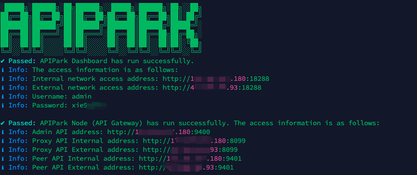
In my experience, you can see the successful deployment interface within 5 to 10 minutes. Then, you can log in to APIPark using your account.

Step 2: Call the OpenAI API.