Breaker Breakers Explained: Types, Safety, and Selection
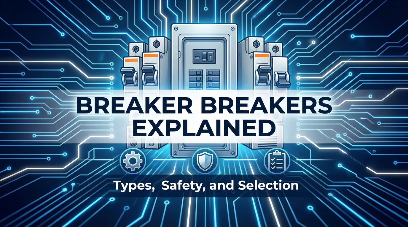


The intricate web of modern life is powered by electricity, an invisible force that fuels our homes, businesses, and industries. While its benefits are immeasurable, electricity also harbors inherent dangers, from overheating wires and potential fires to severe electric shock. Standing as the silent sentinels against these threats are circuit breakers—ingenious devices that have evolved from simple fuses into sophisticated guardians of electrical safety. They are not merely switches that turn power on and off; they are the critical protective mechanisms designed to detect abnormalities in electrical current and instantaneously interrupt the flow, preventing catastrophic damage and safeguarding lives. Understanding these indispensable components, from their fundamental operational principles to their diverse types, critical safety functions, and the meticulous process of their selection, is paramount for anyone involved with electrical systems, from homeowners to seasoned engineers. This comprehensive guide will delve deep into the world of circuit breakers, elucidating their complexities and emphasizing their vital role in our electrically charged world.
1. Introduction: The Unsung Guardians of Electrical Safety
In the modern era, electricity forms the very backbone of our civilization, illuminating our cities, powering our communication networks, and driving our technological advancements. Yet, with this pervasive utility comes an inherent set of risks. An overloaded circuit, a short circuit, or a ground fault can quickly escalate from a minor inconvenience into a serious hazard, capable of causing extensive property damage, initiating devastating fires, or inflicting severe injuries, even fatalities, through electrocution. It is precisely within this critical context that circuit breakers emerge as indispensable components of every electrical system, from the smallest residential dwelling to the largest industrial complex.
The concept of overcurrent protection is not new; rudimentary fuses, which simply melted to break a circuit when current exceeded a safe limit, have been in use for over a century. However, as electrical systems grew in complexity and demand, a more sophisticated, reusable, and precise protective device was needed. This demand spurred the invention and continuous evolution of the circuit breaker. Unlike a fuse, which is a single-use device requiring replacement after it operates, a circuit breaker is designed to be reset after it trips, offering a convenient and reliable solution for repeated fault conditions, provided the underlying issue is resolved.
At its core, a circuit breaker is an automatic electrical switch designed to protect an electrical circuit from damage caused by an overcurrent, which typically results from an overload or a short circuit. Its fundamental role extends beyond mere inconvenience prevention; it is primarily about safety. By rapidly interrupting the flow of electricity when an anomaly is detected, circuit breakers prevent wires from overheating and melting, which could ignite insulation and surrounding materials. They stop potentially deadly currents from flowing through faulty appliances or compromised wiring, thus mitigating the risk of electrical fires and safeguarding human life from lethal shocks. Their silent, vigilant operation ensures the integrity of electrical installations and the continuous, safe operation of countless devices that define our modern existence. This guide embarks on a journey to unravel the intricacies of these essential devices, exploring their various types, the sophisticated mechanisms that enable their protective functions, and the critical considerations involved in selecting the right breaker for any given application.
2. The Fundamental Principles of Circuit Breaker Operation
Beneath the seemingly simple toggle switch of a circuit breaker lies a marvel of engineering, a complex interplay of thermal, magnetic, and mechanical forces orchestrated to perform a single, vital task: to instantaneously interrupt the flow of electricity when a dangerous condition arises. Understanding these fundamental principles is key to appreciating the sophistication and reliability of these electrical guardians.
2.1 Overcurrent Detection: The Senses of a Breaker
The primary function of any circuit breaker is to detect an overcurrent condition. This detection capability is typically achieved through one of two principal mechanisms, or often a combination of both: thermal and magnetic.
2.1.1 Thermal Mechanism: Responding to Sustained Overloads
The thermal trip mechanism is designed to react to sustained overcurrents, which are currents that exceed the circuit's rated capacity but are not necessarily catastrophic short circuits. Imagine plugging too many high-power appliances into a single outlet; the total current drawn will slowly but surely exceed what the wiring and the breaker are designed to safely handle. In such a scenario, the thermal mechanism comes into play.
At the heart of the thermal mechanism is a bimetallic strip. This strip is composed of two different metals, typically bonded together, each possessing a different coefficient of thermal expansion. As electrical current flows through the circuit, it also passes through or near this bimetallic strip, generating heat through resistance (Joule heating). When an overcurrent condition persists, the amount of heat generated increases significantly. Because the two metals in the strip expand at different rates when heated, the bimetallic strip begins to bend or warp. As it bends, it mechanically pushes against a latch or trigger mechanism. Once a predefined bending threshold is reached, this latch is released, initiating the trip sequence and opening the circuit.
The genius of the thermal mechanism lies in its inherent time-delay characteristic. It doesn't trip instantaneously for minor, momentary overloads that are harmless and common (like the brief current surge when a motor starts). Instead, it allows for short, tolerable current excursions, but trips faster as the overcurrent level increases. This time-current relationship is crucial; it ensures that the breaker trips when wires are in danger of overheating, but not so readily that it causes nuisance trips for everyday electrical phenomena.
2.1.2 Magnetic Mechanism: The Instantaneous Response to Short Circuits
In contrast to sustained overloads, a short circuit represents a much more immediate and severe threat. A short circuit occurs when a low-resistance path is created, allowing an enormous surge of current to bypass the normal load. This surge can be thousands of times the normal operating current, generating immense heat and destructive forces almost instantaneously. For these conditions, the thermal mechanism would be too slow, and immediate action is required.
This is where the magnetic trip mechanism proves invaluable. It consists of an electromagnet (a coil of wire) placed in series with the main circuit. When current flows through the coil, it generates a magnetic field. Under normal operating conditions, this magnetic field is relatively weak and has no effect. However, during a severe short circuit, the current surges dramatically, creating an incredibly powerful magnetic field almost instantly. This powerful magnetic field is strong enough to attract an armature, which is a small piece of metal positioned near the electromagnet. The movement of this armature, much like the bimetallic strip, mechanically activates the trip mechanism, causing the breaker to open the circuit with extreme rapidity—often within milliseconds.
The magnetic mechanism provides an instantaneous trip, offering crucial protection against the destructive forces of a short circuit. It is independent of temperature, reacting purely to the magnitude of the current.
2.1.3 Combined Thermal-Magnetic Units: Comprehensive Protection
Many common circuit breakers, particularly Miniature Circuit Breakers (MCBs), incorporate both thermal and magnetic elements, offering comprehensive protection against both types of overcurrent conditions. The thermal element handles sustained overloads with a time delay, preventing wire overheating, while the magnetic element provides instantaneous protection against the violent current surges of short circuits. This synergistic design ensures that the circuit is protected across the entire spectrum of potential overcurrent faults.
2.2 Arc Extinction: Taming the Electrical Fireball
When a circuit breaker opens a circuit under load, especially during a high-current fault condition, the act of separating the electrical contacts creates an electrical arc. This arc is essentially a continuous electrical discharge through the air or other insulating medium, capable of generating extreme heat (thousands of degrees Celsius), intense light, and even plasma. If not properly managed and rapidly extinguished, this arc can sustain the current flow, damage the breaker contacts, melt wiring, ignite flammable materials, or even cause an arc flash explosion, posing severe risks to equipment and personnel.
Circuit breakers are ingeniously designed with features to rapidly extinguish these dangerous arcs:
- Arc Chutes/De-ionizing Plates: Most breakers incorporate arc chutes, which are stacks of metal plates (often made of steel or copper) within an insulating housing. When an arc forms between the separating contacts, the magnetic field generated by the arc itself, or by adjacent coils, forces the arc into these plates. The plates then divide the single, large arc into several smaller, less energetic arcs. As the arcs are forced through the narrow gaps between the plates, they are cooled, elongated, and eventually extinguished as the ionized gases recombine.
- Gas Generation: In some larger industrial breakers, the materials used for arc chutes or surrounding the contacts can generate gas when exposed to the heat of an arc. This gas helps to cool and de-ionize the arc, further assisting in its extinction.
- Rapid Separation: The speed at which the contacts separate is also critical. Faster separation helps to draw out the arc and increase its resistance, making it easier to extinguish.
The ability to safely and quickly extinguish arcs is a hallmark of a high-quality circuit breaker and is fundamental to its role in preventing fires and ensuring overall system safety.
2.3 Mechanical Tripping and Reset: The Physical Interruption
Once the thermal or magnetic detection mechanism has been activated, it triggers a mechanical trip unit. This unit physically separates the main electrical contacts within the breaker, creating an open circuit and thereby stopping the flow of electricity. The breaker's toggle switch typically moves to a "trip" or "off" position, indicating that a fault has occurred. To restore power, the underlying fault must first be identified and resolved. Once the issue is addressed, the breaker can then be manually reset (usually by pushing the toggle completely to the "off" position and then back to "on") to re-close the contacts and re-energize the circuit. This manual reset requirement is a crucial safety feature, preventing immediate re-energization of a potentially faulty circuit without human intervention.
2.4 Key Electrical Parameters
Beyond their operational mechanisms, circuit breakers are defined by several key electrical parameters that dictate their suitability for different applications:
- Voltage Rating: The maximum voltage the breaker is designed to safely operate at and interrupt. This must match or exceed the system voltage.
- Current Rating (Ampere Rating): The continuous current the breaker can carry without tripping. This is typically matched to the wire gauge and the connected load.
- Frequency: The AC frequency (e.g., 50 Hz or 60 Hz) for which the breaker is designed.
- Interrupting Capacity (AIC/kA Rating): Arguably one of the most critical safety parameters, this specifies the maximum fault current (in Amperes or kiloamperes, kA) that the breaker can safely interrupt without being damaged or failing catastrophically. A breaker with insufficient interrupting capacity could explode during a severe short circuit, causing significant damage.
By understanding these fundamental principles, one can grasp the intricate engineering that makes circuit breakers such effective and reliable guardians of our electrical systems, constantly monitoring, detecting, and reacting to protect lives and property.
3. A Deep Dive into Circuit Breaker Types
The world of circuit breakers is far more diverse than what one might encounter in a typical residential panel. Different applications, ranging from a single household outlet to a massive industrial motor or a high-voltage transmission line, demand distinct types of protection. Each circuit breaker type is engineered with specific characteristics, operating principles, and capabilities to address the unique challenges of its intended environment.
3.1 Miniature Circuit Breakers (MCBs): The Everyday Protector
Miniature Circuit Breakers (MCBs) are perhaps the most ubiquitous type, found in almost every modern residential, light commercial, and small industrial electrical panel. They are designed for low-voltage applications, typically up to 100 amps, and are easily identifiable by their compact, standardized sizes, often mounted on a DIN rail.
- Description and Construction: MCBs are characterized by their compact size, enabling a high density of circuits within a small panelboard. They come in single-pole versions (protecting one hot conductor), double-pole versions (protecting two hot conductors, common for 240V appliances), and occasionally triple-pole versions for three-phase systems. Their internal mechanism is generally sealed within a molded plastic case, making them non-serviceable but highly reliable.
- Operating Principle: As discussed, MCBs primarily utilize a thermal-magnetic tripping mechanism. The bimetallic strip handles sustained overloads, offering a time-delay trip, while the magnetic coil provides instantaneous protection against severe short circuits. This dual protection makes them versatile for general circuit protection.
- Trip Curves (Type B, C, D, K, Z): A critical characteristic of MCBs is their trip curve, which defines how quickly the magnetic trip mechanism activates in response to short-circuit currents. This curve is chosen based on the nature of the load the breaker is protecting:
- Type B Curve: Trips instantaneously at 3 to 5 times its rated current. Suitable for resistive loads (e.g., lighting, heating elements) where inrush currents are minimal.
- Type C Curve: Trips instantaneously at 5 to 10 times its rated current. This is the most common type for general-purpose circuits, protecting against overloads and short circuits from moderate inductive loads (e.g., general outlets, small motors, fluorescent lighting).
- Type D Curve: Trips instantaneously at 10 to 20 times its rated current. Designed for highly inductive loads with very high inrush currents (e.g., transformers, X-ray machines, welding equipment, large motors) where a higher tolerance for momentary current spikes is needed.
- Type K Curve: Trips instantaneously at 8 to 12 times its rated current. Often used for motor protection, offering a compromise between B and C curves.
- Type Z Curve: Trips instantaneously at 2 to 3 times its rated current. Extremely sensitive, used for protecting very sensitive electronic equipment (e.g., computers, medical equipment) which cannot tolerate even small overcurrents.
- Applications: MCBs are the workhorses of residential and light commercial electrical systems, protecting circuits for lighting, general-purpose receptacles, small appliances, and often individual fixed loads like water heaters or furnaces.
3.2 Ground Fault Circuit Interrupters (GFCIs): Safeguarding Against Electrocution
Ground Fault Circuit Interrupters (GFCIs) are unique among circuit breakers because their primary purpose is not just to prevent damage to wiring or equipment, but specifically to protect human life from electrocution. They achieve this by detecting very small, potentially lethal leakage currents to ground, often imperceptible to standard breakers.
- Description and Function: A GFCI continuously monitors the balance of current flowing through the "hot" (live) wire and the "neutral" wire of a circuit. In a healthy circuit, the current flowing out on the hot wire should exactly equal the current returning on the neutral wire. If a person accidentally touches a live wire and becomes a path to ground, or if an appliance has an internal fault that causes current to leak to ground, this balance is disrupted.
- Operating Principle: The heart of a GFCI is a current transformer that encircles both the hot and neutral conductors. Under normal conditions, the magnetic fields generated by the outgoing and returning currents cancel each other out. If a ground fault occurs, even a small current (typically 5 milliamperes or 0.005 amps) leaks to ground, creating an imbalance. This imbalance is detected by the transformer, which then induces a current in a sensing coil. This induced current is amplified, and if it exceeds the trip threshold, it quickly (within milliseconds, typically 25ms) activates a solenoid that trips the breaker, cutting off power.
- Types: GFCIs are available in several forms:
- Receptacle GFCIs: These are the most common and easily recognizable, integrated into an electrical outlet. They protect any loads plugged into them and often downstream outlets on the same circuit.
- Breaker GFCIs: These are integrated into the circuit breaker itself and installed in the electrical panel. They protect the entire circuit they control, offering protection for all outlets and devices on that circuit.
- Portable GFCIs: Plug-in devices used for temporary protection in various settings.
- Applications: Electrical codes (such as the National Electrical Code in the US) mandate GFCI protection in areas where water is present or where there's a higher risk of ground faults. This includes bathrooms, kitchens (countertop receptacles), garages, basements, outdoors, crawl spaces, laundry rooms, and areas near swimming pools or hot tubs.
3.3 Arc Fault Circuit Interrupters (AFCIs): Preventing Electrical Fires
While GFCIs protect against ground faults, and MCBs protect against overloads and short circuits, another insidious threat exists: arc faults. An arc fault is an unintended electrical discharge, often caused by damaged insulation, loose connections, or pinched wires, which can generate localized heat intense enough to ignite surrounding materials, leading to electrical fires. Arc Fault Circuit Interrupters (AFCIs) are specifically designed to detect these dangerous arcing conditions.
- Description and Function: AFCIs utilize sophisticated electronic circuitry and digital signal processing to differentiate between harmless arcing (e.g., from a light switch being flipped, a motor commutator operating) and dangerous, sustained arcing that could lead to a fire. They analyze the specific waveform signatures of an arc fault.
- Operating Principle: Unlike simple thermal-magnetic breakers, AFCIs constantly monitor the current waveform for specific "noise" or patterns characteristic of hazardous arcing. They can detect both series arcs (an arc in a single conductor, like a broken wire inside its insulation) and parallel arcs (an arc between two conductors or between a conductor and ground). When these specific patterns are identified, the AFCI trips, interrupting the circuit.
- Types:
- Branch/Feeder AFCI: Installed in the electrical panel, protects the wire run from the panel to the first outlet.
- Combination AFCI (CAFCI): The most common type, protecting against both parallel and series arcs. These are generally required by current electrical codes.
- Outlet AFCI: An AFCI device built into an electrical outlet, similar to a GFCI receptacle, protecting downstream portions of the circuit.
- Applications: Electrical codes increasingly require AFCI protection for most residential circuits, particularly in living rooms, dining rooms, bedrooms, dens, hallways, and similar areas, effectively aiming to prevent electrical fires where occupants sleep or spend significant time.
3.4 Molded Case Circuit Breakers (MCCBs): The Workhorses of Commercial and Industrial Settings
Moving beyond the typical residential panel, Molded Case Circuit Breakers (MCCBs) are the next step up in terms of current rating, interrupting capacity, and customizability. They are widely used in commercial, institutional, and light industrial applications.
- Description and Construction: MCCBs are characterized by their sturdy, integral molded case, made from high-strength insulating materials, which provides insulation and structural integrity for the current-carrying components and the trip mechanism. They typically handle currents from 100 amps up to 2500 amps and have significantly higher interrupting ratings (kA) than MCBs. They can be single, double, three, or four-pole.
- Operating Principle: MCCBs can feature either thermal-magnetic trip units (similar to MCBs but on a larger scale) or, more commonly, sophisticated electronic trip units.
- Electronic Trip Units: These units utilize microprocessors to monitor current and provide precise, adjustable protection settings. This is a key advantage over MCBs. Users can precisely set overload (long-time delay), short-circuit (short-time delay), instantaneous trip levels, and sometimes ground fault protection. This adjustability is crucial for coordination with other protective devices in complex electrical systems.
- Adjustable Trip Units: The ability to customize trip settings allows engineers to fine-tune the breaker's response to different fault conditions, ensuring that only the faulty section of a system is disconnected, while the rest remains operational (selective coordination).
- Interrupting Ratings: MCCBs are designed with much higher interrupting capacities (often ranging from 10 kA to 200 kA) to safely handle the larger fault currents common in commercial and industrial environments.
- Applications: MCCBs serve as main service disconnects, feeder circuit protection, and branch circuit protection for larger loads such as motors, HVAC systems, industrial machinery, and distribution panels in commercial buildings, schools, hospitals, and factories.
3.5 Insulated Case Circuit Breakers (ICCBs) & Low Voltage Power Circuit Breakers (LVPCBs): Heavy-Duty Protection
For the most demanding low-voltage applications, where extremely high current ratings and interrupting capacities are required, Insulated Case Circuit Breakers (ICCBs) and Low Voltage Power Circuit Breakers (LVPCBs) come into play. These are robust, heavy-duty devices designed for main switchboards and large distribution boards.
- Description and Construction: These breakers are significantly larger and more rugged than MCCBs. ICCBs typically have an insulated housing that can be drawn out for maintenance, while LVPCBs (sometimes referred to as Air Circuit Breakers or ACBs) are built on a more open frame structure, but both are designed for very high current (up to 6000+ amps) and fault levels. They often feature "draw-out" construction, allowing the breaker to be safely disconnected and removed from the switchgear for inspection or replacement without de-energizing the entire busbar system, greatly simplifying maintenance.
- Operating Principle: ICCBs and LVPCBs almost exclusively use advanced electronic trip units, offering the highest degree of precision and adjustability for protective functions. These trip units provide comprehensive protection, including long-time, short-time, instantaneous, and highly sophisticated ground fault protection, enabling precise coordination in large, complex power distribution systems. They employ robust arc extinguishing techniques, often involving large arc chutes and sometimes magnetic blow-out coils, to manage the immense energy of fault arcs.
- Applications: These breakers are critical components in the main power distribution systems of large industrial plants, heavy commercial facilities, data centers, hospitals, and utility substations. They protect primary feeders, large motor control centers, and provide overall system protection.
3.6 High Voltage Circuit Breakers (HV Breakers): For the Grid's Backbone
While this guide primarily focuses on low-voltage circuit breakers relevant to everyday applications, it's worth briefly acknowledging High Voltage Circuit Breakers (HV Breakers). These colossal devices operate at voltage levels ranging from thousands of volts to hundreds of thousands of volts, typically found in power generation, transmission, and distribution substations.
- Brief Mention of Types: HV breakers utilize various mediums for arc extinction, given the extreme energy involved:
- SF6 (Sulfur Hexafluoride) Breakers: Most common today, SF6 gas has excellent dielectric and arc-quenching properties.
- Vacuum Breakers: Use a vacuum to extinguish arcs, suitable for medium-high voltage applications.
- Oil Breakers: Older technology, using insulating oil to quench arcs.
- Air Blast Breakers: Use a blast of compressed air.
- Purpose: HV breakers are essential for protecting large-scale electrical infrastructure such as transmission lines, large transformers, and generators, ensuring the stability and reliability of the entire electrical grid. Their design and operation are significantly more complex due to the immense voltages and currents they must handle.
This detailed exploration of circuit breaker types reveals the specialized engineering required to meet the diverse protection needs across the entire spectrum of electrical applications, from a simple light switch to the national power grid. Each type plays a unique and indispensable role in maintaining electrical safety and system integrity.
4. Paramount Importance of Circuit Breaker Safety Functions
The raison d'être of any circuit breaker lies squarely in its safety functions. These devices are not merely passive components; they are active, vigilant guardians constantly monitoring the electrical pulse of a system, ready to act decisively when danger looms. Their ability to preemptively mitigate hazards is what makes them utterly indispensable in our electrically powered world.
4.1 Overload Protection: Preventing the Slow Burn
An overload occurs when the total current drawn by connected loads on a circuit exceeds the circuit's design capacity. Unlike a short circuit, which is an immediate and dramatic surge, an overload is often a gradual buildup of excessive current. Imagine plugging in a space heater, a vacuum cleaner, and a microwave oven simultaneously on a circuit rated for only 15 amps; the cumulative draw might reach 30 amps. This excessive current, while not an instantaneous catastrophe, causes the wiring to overheat over time.
The consequences of unchecked overloads are severe: * Wire Insulation Degradation: Prolonged overheating causes the plastic or rubber insulation around wires to break down, become brittle, and eventually crack or melt. This exposes bare conductors, leading to potential short circuits, ground faults, and direct contact hazards. * Fire Hazard: Melted insulation is highly flammable, and the heat generated by overloaded wires can easily ignite surrounding combustible materials, leading to devastating electrical fires within walls or ceilings. * Equipment Damage: Appliances and equipment connected to an overloaded circuit can also suffer damage due to excessive heat or voltage drops.
The thermal mechanism within a circuit breaker is specifically designed to provide this crucial overload protection. It trips when the sustained heat from the overcurrent causes the bimetallic strip to bend. The "time-current curve" characteristic of the breaker dictates that the higher the overload current, the faster the breaker will trip. This intelligent response ensures that minor, temporary current spikes (like motor startup) don't cause nuisance trips, but persistent, dangerous overloads are promptly interrupted before any damage can occur.
4.2 Short Circuit Protection: Avertive of Explosive Forces
A short circuit is the most abrupt and dangerous fault condition. It happens when an unintended, low-resistance path is created between a "hot" (live) conductor and a "neutral" conductor, or between two hot conductors, or between a hot conductor and ground. This could be due to damaged insulation, a loose wire making contact, or even a metallic object accidentally falling across terminals.
The immediate effect of a short circuit is a massive, instantaneous surge of current—often hundreds or even thousands of times the normal operating current. The dangers are profound: * Arc Flash and Arc Blast: The sudden, immense current can generate an extremely high-temperature electrical arc. This arc can vaporize metal, creating a superheated plasma that expands explosively (an arc blast), projecting molten metal and causing severe burns, concussive injuries, and even fatalities to anyone nearby. * Explosive Failure of Equipment: The enormous mechanical forces generated by the magnetic fields of a short circuit can physically destroy wires, equipment, and even the circuit breaker itself if it's not adequately rated. * Fire: The extreme heat from an arc or rapidly melting components can instantly ignite adjacent materials.
The magnetic mechanism within a circuit breaker is solely responsible for providing this instantaneous short circuit protection. It reacts almost immediately to the massive current surge, electromagnetically tripping the breaker within milliseconds. A critical parameter for short circuit protection is the breaker's Interrupting Capacity (AIC - Ampere Interrupting Capacity, or kA rating). This rating specifies the maximum fault current that the breaker can safely interrupt without itself failing catastrophically. Installing a breaker with an insufficient AIC rating in a circuit where the available fault current (the maximum current that could flow during a short circuit) is higher is a severe safety violation and an invitation to disaster. During a short circuit, such a breaker could literally explode, failing to clear the fault and exacerbating the hazard.
4.3 Ground Fault Protection (GFCI): Preventing Electrocution
Unlike overloads and short circuits which primarily protect wiring and equipment, ground fault protection, delivered by GFCIs, is specifically designed to protect human life from electrocution. A ground fault occurs when current deviates from its intended path and finds an unintended route to ground, often through a person who has come into contact with a live wire or a faulty appliance.
The danger of electric shock is that even a small amount of current (as little as 50 milliamperes, 0.05 amps) flowing through the human body can be fatal, disrupting heart rhythm or paralyzing respiratory muscles. Standard thermal-magnetic breakers are ineffective against such small leakage currents because these currents are far below the breaker's trip rating for overloads or short circuits.
GFCIs work by detecting minute imbalances in current between the live and neutral wires. If a person is being shocked, current is leaking to ground through their body, creating this imbalance. The GFCI detects this imbalance (typically as low as 4-6 milliamperes) and trips within milliseconds (e.g., 25ms), long before a dangerous amount of energy can pass through the body. This rapid response is why GFCIs are mandated in wet locations and other high-risk areas, providing a life-saving barrier against accidental electrocution.
4.4 Arc Fault Protection (AFCI): Preventing Fires from Hidden Damage
Arc faults are particularly insidious because they can occur at current levels well below an overload threshold and without a direct ground path, making them invisible to traditional breakers and even GFCIs. They are often caused by: * Damaged Insulation: Nicks, cuts, or deterioration from age, heat, or rodents. * Loose Connections: At outlets, switches, or within junction boxes. * Pinched or Kinked Wires: From furniture, nails, or staples. * Over-extended Cords: Causing internal wire breaks.
These conditions can lead to intermittent or sustained arcing, generating localized temperatures over 10,000°F (5,500°C)—hot enough to melt wire, vaporize insulation, and ignite nearby combustible materials like wood framing, curtains, or insulation.
AFCIs are the only devices capable of detecting these dangerous arcing signatures. Through advanced electronic algorithms, they analyze the unique current and voltage waveforms associated with hazardous arcs, distinguishing them from harmless operational arcing (e.g., when plugging in an appliance). By tripping quickly when a dangerous arc fault is detected, AFCIs significantly reduce the risk of electrical fires originating from damaged wiring, loose connections, or compromised extension cords, providing a crucial layer of fire prevention that conventional breakers cannot offer.
4.5 System Isolation and Maintenance: Enabling Safe Work Environments
Beyond their automatic protection functions, circuit breakers also serve a critical role in enabling safe manual operation and maintenance. By manually switching a breaker to the "OFF" position, an electrician or technician can effectively isolate a specific circuit or piece of equipment from the main power supply. This intentional de-energization is fundamental to safe electrical work.
Furthermore, in commercial and industrial settings, circuit breakers are often part of a larger "Lockout/Tagout" (LOTO) procedure. This formal safety protocol involves physically locking the breaker in the "OFF" position and attaching a tag to it, indicating that work is being performed on the circuit and it must not be re-energized. This prevents accidental energization by unauthorized personnel, ensuring that maintenance or repair work can be carried out without the risk of electric shock or arc flash incident. This function underscores the breaker's dual role as both an automatic protector and a vital manual safety switch.
In summary, the multifaceted safety functions of circuit breakers—protecting against overloads, short circuits, ground faults, and arc faults—form a comprehensive shield around our electrical systems, guarding against equipment damage, preventing devastating fires, and most importantly, preserving human life. Their presence is a non-negotiable requirement for any safely designed electrical installation.
APIPark is a high-performance AI gateway that allows you to securely access the most comprehensive LLM APIs globally on the APIPark platform, including OpenAI, Anthropic, Mistral, Llama2, Google Gemini, and more.Try APIPark now! 👇👇👇
5. The Art and Science of Circuit Breaker Selection
Selecting the correct circuit breaker for a given application is not a trivial task; it is a critical engineering decision that directly impacts the safety, reliability, and efficiency of an entire electrical system. A mismatch can lead to nuisance tripping, equipment damage, or, most dangerously, a catastrophic failure of the protection device when it's needed most. This section delves into the meticulous criteria that guide proper circuit breaker selection.
5.1 Amperage Rating (Current Rating): The Core Match
The amperage rating, often simply referred to as the "size" of the breaker, is the continuous current (in Amperes) that the breaker is designed to carry without tripping. This is perhaps the most fundamental selection criterion.
- Matching to Wire Gauge: The breaker's amperage rating must always be matched to the ampacity of the conductors (wires) it protects. Wires are sized based on the maximum current they can safely carry without overheating. The breaker's rating must be equal to or less than the ampacity of the wire to ensure that the breaker trips before the wire can overheat and melt its insulation. For example, a common 14-gauge copper wire typically has an ampacity of 15 amps, thus requiring a 15-amp breaker. A 12-gauge wire, rated for 20 amps, would get a 20-amp breaker. Never install a breaker with a higher amperage rating than the wire's ampacity, as this defeats the primary purpose of overload protection.
- Matching to Connected Load: The breaker should also be sized appropriately for the expected electrical load. While it must not exceed the wire's capacity, it also needs to be large enough to handle the normal operating current of all connected devices.
- The 80% Rule for Continuous Loads: For circuits supplying continuous loads (loads that operate for 3 hours or more, such as lighting in a commercial building or a motor that runs for extended periods), electrical codes generally require that the maximum continuous current draw not exceed 80% of the breaker's rating. This provides a safety margin to prevent nuisance tripping and reduce heat buildup in the breaker itself. For instance, a 20-amp breaker should only continuously carry 16 amps (20A * 0.8).
- Examples: A general-purpose lighting circuit might use a 15-amp breaker, while a dedicated kitchen appliance circuit or garage receptacle circuit might use a 20-amp breaker. Large appliances like electric stoves, water heaters, or central air conditioning units will require higher-rated breakers (e.g., 30A, 40A, 50A), usually double-pole.
5.2 Voltage Rating: System Compatibility
The voltage rating of a circuit breaker specifies the maximum system voltage it can safely interrupt.
- Matching or Exceeding System Voltage: The breaker's voltage rating must be equal to or greater than the maximum voltage of the circuit it is protecting. For example, a breaker rated for 120V AC should only be used in 120V systems, while a breaker rated for 240V AC can be used in 240V or 120/240V systems. Using a breaker with a voltage rating lower than the system voltage is extremely dangerous, as it may not be able to safely interrupt an arc during a fault, leading to catastrophic failure.
- Single-Pole vs. Double-Pole:
- Single-pole breakers (typically 120V in North America) protect a single hot conductor and are used for circuits supplying standard outlets and lighting.
- Double-pole breakers (typically 240V in North America or 400V three-phase in Europe) protect two hot conductors simultaneously and are used for high-voltage appliances like electric ranges, clothes dryers, and central air conditioning units, or for three-phase loads.
5.3 Interrupting Capacity (AIC/kA Rating): The Ultimate Safety Threshold
This is arguably one of the most critical, yet often overlooked, safety parameters. The Interrupting Capacity (AIC - Ampere Interrupting Capacity, or kA for kiloamperes) specifies the maximum fault current that a circuit breaker can safely interrupt without being damaged or failing catastrophically.
- Why it's Critical: During a severe short circuit, the available fault current can be enormous, potentially thousands of amperes. If a breaker's AIC rating is lower than the actual available fault current at its location in the electrical system, it will not be able to safely interrupt the fault. Instead, it could explode, vaporize, or weld its contacts shut, failing to clear the fault and leading to an arc flash, fire, or extensive damage to the electrical panel and surrounding property.
- Calculating Available Fault Current: Determining the available fault current at various points in an electrical system is a complex calculation that requires specialized electrical engineering knowledge. It depends on factors like the utility transformer size, impedance of service conductors, and the distance from the source. This calculation is a fundamental part of proper electrical system design.
- Importance for Safety: Always ensure that the selected breaker's AIC rating is equal to or greater than the maximum available fault current at the point of installation. For residential applications, 10 kA AIC is common, but in commercial or industrial settings, especially close to large utility transformers, breakers with 22 kA, 42 kA, 65 kA, or even higher AIC ratings may be required.
5.4 Trip Curve Characteristics (MCB Specific): Tailoring Response to Load Type
As discussed in Section 3.1, for Miniature Circuit Breakers (MCBs), the trip curve (e.g., Type B, C, D) is crucial for matching the breaker's magnetic trip response to the characteristics of the load.
- Consideration of Inrush Currents: Certain loads, particularly inductive loads like motors, transformers, or certain types of lighting, draw a momentarily very high "inrush" current when they first start up. While this surge is normal and harmless, a breaker with too sensitive a magnetic trip (like a Type B) would nuisance trip.
- Selecting the Right Curve:
- Type B: For purely resistive loads or circuits with very low inrush currents (e.g., heating, incandescent lighting).
- Type C: The most common general-purpose choice, suitable for a mix of resistive and moderate inductive loads (e.g., general outlets, fluorescent lighting, small appliances).
- Type D: For loads with very high inrush currents (e.g., large motors, transformers, welding equipment, X-ray machines). Using a D-curve prevents nuisance tripping during normal startup.
- Implications: Choosing the wrong trip curve can either lead to annoying nuisance trips (if too sensitive) or, more dangerously, fail to provide adequate short-circuit protection for sensitive electronics (if too tolerant).
5.5 Number of Poles: Matching Phases and Voltage
The number of poles on a breaker corresponds to the number of conductors it simultaneously opens to interrupt a circuit.
- Single-Pole: For single-phase, 120V circuits (in North America). Protects one hot wire.
- Double-Pole: For single-phase, 240V circuits (in North America) or for two-phase protection in three-phase systems. Protects two hot wires and physically links their tripping mechanisms, ensuring both legs of the circuit open simultaneously.
- Three-Pole: For three-phase systems (e.g., 208V, 400V, 480V). Protects all three hot conductors, ensuring simultaneous interruption of all phases during a fault.
5.6 Specific Protection Needs: GFCI, AFCI, and Specialty Breakers
Beyond basic overcurrent protection, specific circuits may require enhanced safety features:
- GFCI Requirements: Mandated in locations susceptible to ground faults (wet areas like bathrooms, kitchens, outdoors, garages, etc.) to protect against electrocution.
- AFCI Requirements: Mandated in living spaces (bedrooms, living rooms, etc.) to protect against electrical fires caused by arc faults.
- Specialty Breakers: Some applications may require highly specialized breakers. For instance, motor protection circuit breakers combine thermal-magnetic protection with overload elements specifically tailored for motor starting characteristics and locked-rotor conditions.
5.7 Environmental Considerations: Where the Breaker Lives
The operating environment can significantly impact breaker performance and longevity.
- Temperature Derating: Breakers are typically rated for operation at a specific ambient temperature (e.g., 40°C or 104°F). If a breaker is installed in an environment with a significantly higher ambient temperature (e.g., an industrial furnace room), its continuous current carrying capacity must be "derated" (reduced) to prevent premature tripping or damage. Conversely, very cold environments can affect magnetic trip characteristics.
- Enclosures (NEMA/IP Ratings): For dusty, wet, corrosive, or hazardous locations, circuit breakers must be housed in appropriate enclosures (e.g., NEMA 3R for outdoor rain protection, NEMA 4X for corrosion resistance, NEMA 7/9 for hazardous classified locations) to protect the internal components from environmental degradation and prevent ignition of explosive atmospheres.
5.8 Manufacturer and Certifications: Quality Assurance
Always select circuit breakers from reputable manufacturers that comply with recognized safety standards.
- Certifications: Look for certifications from recognized testing laboratories:
- UL (Underwriters Laboratories): Common in North America.
- IEC (International Electrotechnical Commission): Widely used internationally, particularly in Europe.
- CSA (Canadian Standards Association): For Canada.
- These certifications ensure the breaker has been rigorously tested and meets stringent safety and performance criteria. Using uncertified or counterfeit breakers poses serious risks.
5.9 System Coordination: The Symphony of Protection
In complex electrical systems (especially commercial and industrial), selective coordination is a critical design objective. This means that during a fault, only the circuit breaker immediately upstream of the fault should trip, isolating the smallest possible section of the system while allowing the rest to remain operational.
- Time-Current Coordination Studies: Achieving selective coordination requires detailed time-current coordination studies. These studies involve plotting the time-current curves of all protective devices in a system on a single graph to ensure their tripping characteristics overlap correctly, ensuring that a downstream breaker clears a fault before an upstream breaker. Adjustable electronic trip units in MCCBs and LVPCBs are essential for achieving precise coordination.
The systematic consideration of these factors ensures that the selected circuit breaker not only provides the necessary protection for the circuit but also integrates seamlessly into the overall electrical system, operating safely and reliably for years to come. This meticulous process transforms breaker selection from a simple choice into an informed engineering decision.
6. Installation, Maintenance, and Best Practices
The most perfectly engineered circuit breaker is only as effective as its installation and the ongoing care it receives. Proper installation, diligent maintenance, and adherence to best practices are not merely recommendations; they are fundamental requirements for ensuring the long-term safety, reliability, and optimal performance of any electrical system.
6.1 Proper Installation: Precision from the Start
The correct installation of a circuit breaker is the bedrock of its effectiveness. Mistakes made during installation can compromise its protective capabilities, lead to nuisance tripping, or create significant safety hazards.
- Adherence to Codes and Standards: Foremost, all installations must rigorously follow local electrical codes (e.g., National Electrical Code (NEC) in the United States, BS 7671 in the UK, IEC standards internationally) and manufacturer instructions. These codes represent the minimum safety requirements and are legally binding.
- Correct Breaker Type and Rating: As extensively discussed, ensuring the breaker's voltage, amperage, interrupting capacity, and specific protection type (GFCI, AFCI, trip curve) match the circuit requirements is paramount. Incorrect sizing or type is a dangerous oversight.
- Secure Connections: All electrical connections to the breaker terminals (load wires and busbar connections) must be clean, tight, and free from insulation within the terminal lug. Loose connections are a common cause of overheating, arcing, and nuisance tripping. Use a calibrated torque wrench to tighten terminal screws to the manufacturer's specified torque values. Overtightening can strip threads or damage conductors, while undertightening causes high resistance and heat.
- Wire Sizing and Insulation: Ensure the wire gauge connected to the breaker is appropriate for its amperage rating. The wire insulation must be intact and properly stripped, avoiding nicks or damage.
- Panelboard Integrity: Breakers must be securely seated in the panelboard's busbar connection. Any rocking or looseness indicates an improper connection that could lead to arcing and overheating. Ensure correct polarity (hot to breaker, neutral to neutral bar, ground to ground bar).
- Clear Labeling: Every circuit breaker in a panelboard must be clearly and accurately labeled to identify the specific circuit or loads it controls. This is crucial for safe operation, troubleshooting, and emergency response. Ambiguous labeling can lead to confusion and dangerous mistakes during maintenance or power restoration.
- Physical Space and Ventilation: Ensure adequate space around breakers for heat dissipation and safe operation. Overcrowding in panels can lead to heat buildup and compromised breaker performance. The panel cover must be securely in place, and all unused openings in the panel (knockouts) must be covered with appropriate blanks to prevent accidental contact with live parts.
6.2 Regular Maintenance: Vigilance for Longevity
While circuit breakers are largely "fit and forget" devices in residential settings, larger installations, especially in commercial and industrial environments, benefit significantly from periodic maintenance.
- Visual Inspections: Regularly inspect circuit breakers and panelboards for any signs of damage, wear, or overheating. Look for:
- Discoloration or scorching on the breaker or panel interior.
- Burn marks or melted insulation on wires or terminals.
- Loose wires or connections (though this often requires a qualified technician to check internal connections).
- Dust, debris, or pests inside the panel.
- Corrosion on terminals or busbars.
- Audible buzzing or humming sounds (beyond normal operation).
- Breakers that feel unusually hot to the touch.
- Exercise Breakers (Trip and Reset): For many types of breakers, particularly MCCBs and LVPCBs, it's a recommended practice to "exercise" them annually. This involves manually switching the breaker to the "OFF" position and then back to "ON" (or using the integrated trip button if available). This helps to keep the mechanical components free, prevents rust or stiffness in the trip mechanism, and ensures it will operate smoothly when needed. For critical circuits, this should be done during scheduled downtime or with proper LOTO procedures.
- Professional Testing: For critical commercial and industrial installations with larger, more complex breakers (MCCBs, LVPCBs), periodic professional testing is essential. This often involves:
- Primary Injection Testing: High current is injected through the breaker's main contacts to verify the integrity of the current path and the trip unit.
- Secondary Injection Testing: A test set is connected directly to the electronic trip unit to verify its calibration and functionality across its entire operating curve (long-time, short-time, instantaneous, ground fault).
- Insulation Resistance Testing (Megger Testing): To check the integrity of the insulation within the breaker. These tests ensure the breaker will trip reliably at its specified settings under actual fault conditions.
6.3 Troubleshooting Common Breaker Issues: Diagnosing the Problem
When a circuit breaker trips, it's signaling a problem. Understanding common issues helps in diagnosing and resolving them safely.
- Frequent Tripping:
- Overload: The most common cause. Too many devices on one circuit. Unplug some devices or redistribute loads.
- Short Circuit: Often indicated by an immediate, loud "bang" or flash before tripping. Could be a faulty appliance, damaged wiring, or a loose connection causing conductors to touch. Requires immediate investigation and repair.
- Ground Fault (GFCI trips): A current leak to ground, often in wet areas. Unplug all devices on the circuit and reset. If it holds, plug devices back in one by one to identify the faulty appliance. If it still trips with nothing plugged in, there might be a wiring issue.
- Arc Fault (AFCI trips): Indicates a dangerous arc. Could be damaged wiring, loose connections, or a faulty appliance. Unplug devices, check cords, and if it still trips, professional help is needed to inspect wiring.
- Loose Connections: High resistance from loose connections can generate heat, causing thermal tripping.
- Faulty Breaker: Rarely, the breaker itself may be faulty and tripping prematurely. This can be diagnosed by a qualified electrician.
- Breaker Not Holding Reset: If a breaker immediately trips again after being reset, it indicates a persistent fault (short circuit, severe overload, or ground fault). Do not repeatedly try to reset it; investigate the cause.
- Warm Breaker/Panel: A warm breaker or panel can be normal if carrying a heavy load. However, if it's excessively hot, discolored, or accompanied by a burning smell, it indicates an issue (overload, loose connection) and requires immediate attention.
6.4 Lockout/Tagout (LOTO): The Ultimate Safety Protocol
In industrial and commercial environments, particularly during maintenance or repair of machinery or electrical equipment, Lockout/Tagout (LOTO) procedures are mandatory safety protocols.
- Procedure: LOTO involves physically placing a lock on the circuit breaker (or other energy-isolating device) in its "OFF" or de-energized position and attaching a tag. The tag warns others not to re-energize the circuit and identifies the person performing the work.
- Purpose: This critical procedure prevents the accidental or unauthorized re-energization of circuits or equipment, thereby protecting personnel from unexpected startup, electric shock, or arc flash during servicing. It underscores the importance of the breaker not only as an automatic protector but also as a reliable manual disconnect.
By rigorously adhering to these installation, maintenance, and troubleshooting best practices, the full safety potential of circuit breakers can be realized, ensuring that electrical systems operate safely, efficiently, and without unforeseen interruptions or hazards.
7. Beyond Electrical Breakers: The Concept of Gateways in Modern Systems
While our primary focus has been on the robust, physical circuit breakers that vigilantly guard our electrical flows, it's imperative to recognize that the concept of a "breaker" or a "guardian" is not exclusive to the realm of electricity. In the vast and intricate landscape of digital systems, particularly within modern software architectures and the burgeoning field of Artificial Intelligence, similar critical control points and protective mechanisms are indispensable. These digital counterparts, designed to manage information flow, ensure security, streamline operations, and facilitate communication between disparate systems, are frequently referred to as "gateways." Just as an electrical breaker monitors and controls power, a digital gateway monitors and controls data, ensuring its safe and efficient transit.
7.1 What is a Digital Gateway?
Broadly speaking, a digital gateway acts as an intermediary or an access point between two different networks, systems, or protocols. Its fundamental role is to manage the flow of data, translating protocols, enforcing security policies, and directing traffic efficiently. Without gateways, disparate digital systems would struggle to communicate, much like two people speaking different languages without a translator.
Examples of digital gateways range from: * Network Routers: Which are essentially gateways connecting local networks to the internet, translating network addresses and routing data packets. * Protocol Translators: Devices or software that convert data from one communication protocol to another (e.g., between an IoT device's proprietary protocol and a standard web protocol). * Payment Gateways: Securely processing credit card transactions between a merchant's website and banking networks.
7.2 The Significance of an API Gateway
Among the most crucial types of digital gateways in modern software development is the API gateway. In today's world of microservices architectures, where applications are broken down into smaller, independently deployable services, an API gateway becomes the single entry point for all client requests. Instead of clients needing to know the addresses and protocols of dozens or hundreds of individual microservices, they simply interact with the API gateway.
The functions of an API gateway are multifaceted and critical for the health and performance of distributed systems:
- Authentication and Authorization: Verifying the identity of clients and ensuring they have the necessary permissions to access requested resources, acting as the first line of defense.
- Request Routing: Directing incoming client requests to the appropriate backend microservice, abstracting away the complexity of the internal architecture.
- Rate Limiting: Protecting backend services from being overwhelmed by too many requests from a single client, preventing denial-of-service attacks or unfair resource consumption.
- Load Balancing: Distributing incoming requests across multiple instances of a service to ensure optimal performance and availability.
- Caching: Storing frequently accessed responses to reduce latency and load on backend services.
- Monitoring and Logging: Centralizing the collection of metrics and logs for all API calls, providing crucial insights into system health and usage patterns.
- Protocol Translation: Converting client requests from one protocol (e.g., HTTP/REST) to another (e.g., gRPC, messaging queues) required by backend services.
- Response Transformation: Aggregating responses from multiple services and transforming them into a single, client-friendly format.
In essence, an API gateway acts as a "traffic cop" and a "bouncer" for digital services, ensuring efficient, secure, and controlled access to an application's backend functionalities.
7.3 Introducing APIPark: An Open Source AI Gateway & API Management Platform
The rapid advancement of Artificial Intelligence, particularly Large Language Models (LLMs), has introduced new complexities into software development. Integrating and managing numerous AI models, each with potentially different APIs, authentication methods, and usage patterns, presents a significant challenge. This is precisely where specialized digital gateways, like APIPark, offer an invaluable solution.
APIPark is an innovative open-source AI gateway and API management platform designed to simplify the integration, management, and deployment of both AI and traditional REST services. It bridges the gap between disparate AI models and the applications that leverage them, much like an electrical breaker standardizes protection for diverse loads.
Here’s how APIPark acts as a crucial digital gateway:
- Quick Integration of 100+ AI Models: APIPark provides a unified management system for connecting to a vast array of AI models, abstracting away their individual nuances in authentication and usage tracking. This means developers don't have to learn a new integration method for every new AI model they want to use.
- Unified API Format for AI Invocation: A standout feature, APIPark standardizes the request data format across all integrated AI models. This prevents application-level changes when an underlying AI model is swapped out or a prompt is refined, significantly reducing maintenance costs and increasing developer agility.
- Prompt Encapsulation into REST API: Users can rapidly combine specific AI models with custom prompts to create new, specialized REST APIs. For instance, one could easily create an API for sentiment analysis or language translation, making advanced AI functionalities accessible as simple API calls.
- End-to-End API Lifecycle Management: Beyond just AI, APIPark provides comprehensive tools for managing the entire lifecycle of APIs, from design and publication to invocation and eventual decommissioning. It assists with traffic forwarding, load balancing, and versioning of published APIs, similar to how a robust electrical system manages different circuit loads.
- Performance Rivaling Nginx: Demonstrating its robust engineering, APIPark can achieve over 20,000 transactions per second (TPS) with modest hardware (8-core CPU, 8GB memory), and supports cluster deployment for handling massive traffic volumes.
- Security and Control: Like a diligent electrical breaker, APIPark offers crucial security features such as independent API and access permissions for each tenant (team), and subscription approval features, ensuring that API resources are accessed only by authorized callers, thereby preventing unauthorized API calls and potential data breaches.
In essence, APIPark streamlines the complexities of AI integration and API management, offering efficiency, enhanced security, and optimized data utilization for developers, operations personnel, and business managers alike. Its open-source nature (Apache 2.0 license) makes it accessible for startups, while a commercial version provides advanced features and professional support for enterprises.
7.4 Addressing Complex Protocols with Gateways: Mentioning "MCP"
The digital landscape is also characterized by a myriad of communication protocols, each designed for specific purposes. Just as an electrical system relies on standardized voltages and frequencies, digital systems depend on defined protocols for orderly communication. Gateways often play a crucial role in managing and translating these protocols.
In specialized domains, particularly within AI and large language models (LLMs) that APIPark helps manage, highly specific communication and context management protocols become essential for seamless interaction. For instance, sophisticated systems might utilize a "Model Context Protocol" (MCP) to standardize how conversational context, user session data, or specific model parameters are handled across different AI services or between an application and an LLM. While distinctly different from electrical safety devices, these digital protocols, managed and orchestrated by gateways, ensure the predictable and reliable operation of complex AI systems, just as a circuit breaker ensures the predictable and reliable operation of an electrical circuit. API gateways, through their ability to abstract and translate, can facilitate the integration of systems adhering to such specialized protocols, providing a unified interface for developers. This abstraction is key to managing complexity in modern, interconnected digital ecosystems.
This section highlights that the core principles of protection, control, and management, embodied so clearly by electrical circuit breakers, find their equally critical counterparts in the digital domain through the intelligent design and deployment of various types of gateways, including advanced solutions like APIPark.
8. Conclusion: The Ever-Evolving Role of Protection
From the humble bimetallic strip reacting to an overloaded wire to the sophisticated electronic algorithms detecting an insidious arc fault, circuit breakers stand as the vigilant guardians of our electrical infrastructure. We have traversed their fundamental principles, delving into the precise mechanics of thermal and magnetic tripping, the crucial art of arc extinction, and the intricate design variations that yield Miniature Circuit Breakers (MCBs), Ground Fault Circuit Interrupters (GFCIs), Arc Fault Circuit Interrupters (AFCIs), and the heavy-duty Molded Case Circuit Breakers (MCCBs) and Low Voltage Power Circuit Breakers (LVPCBs). Each type, meticulously engineered for its specific role, forms an indispensable layer in the comprehensive defense against electrical hazards—overloads, short circuits, ground faults, and arc faults—that threaten both property and life.
The meticulous process of selecting the right circuit breaker is far more than a simple purchase; it's an informed engineering decision that demands careful consideration of amperage, voltage, interrupting capacity, trip curve characteristics, and specific application needs. An incorrectly specified breaker can undermine the entire safety scheme, leading to catastrophic consequences. Furthermore, the longevity and effectiveness of these protective devices are inextricably linked to proper installation, adherence to electrical codes, and diligent maintenance practices, including regular inspections and, for larger systems, professional testing.
Yet, as we embrace an increasingly complex technological landscape, the concept of "protection" and "control" extends beyond the physical realm of electricity. In the digital world, where flows of data replace flows of current, sophisticated control points known as gateways serve an analogous function. These digital guardians, whether they are network routers, protocol translators, or advanced API gateways and AI gateways, manage the intricate flow of information, enforce security policies, and abstract complexity to ensure the safe, efficient, and reliable operation of interconnected systems. Platforms like APIPark, through their comprehensive API management capabilities and support for diverse protocols, exemplify this critical function in the AI-driven era, standardizing interactions and safeguarding digital assets.
Ultimately, whether we speak of an electrical breaker that instantaneously interrupts a dangerous current, or a digital gateway that orchestrates the flow of data across complex AI models and microservices, the underlying imperative remains the same: to create robust, resilient, and inherently safe systems. The commitment to understanding, properly implementing, and maintaining these protective mechanisms—both physical and digital—is not just a matter of compliance, but a fundamental responsibility for ensuring the uninterrupted and secure operation of the technologies that power our modern world. As technology evolves, so too must our methods of protection, continually adapting to new challenges and ensuring safety remains at the forefront of innovation.
9. Frequently Asked Questions (FAQs)
Q1: What is the primary difference between a fuse and a circuit breaker? A1: The primary difference lies in reusability. A fuse is a single-use device containing a metal wire or strip that melts and breaks the circuit when an overcurrent occurs, requiring replacement after it trips. A circuit breaker, on the other hand, is a reusable automatic electrical switch that trips (opens the circuit) during an overcurrent but can be reset manually to restore power once the fault condition has been cleared. Circuit breakers also offer more sophisticated protection types, such as ground fault and arc fault interruption, which fuses generally do not.
Q2: How do I know if my circuit breaker is faulty, and when should I replace it? A2: Signs of a faulty circuit breaker include frequent, unexplained tripping (when there's no obvious overload or short circuit), the breaker feeling unusually hot to the touch (beyond normal warmth), visible scorch marks or discoloration on the breaker or panel, or if it fails to hold a reset after a fault has been cleared. You should consider replacing a breaker if it consistently trips without cause, if it appears physically damaged, or if it's an older model that doesn't meet current safety standards (e.g., if you're upgrading to GFCI or AFCI protection). Always consult a qualified electrician for diagnosis and replacement to ensure safety and code compliance.
Q3: What are GFCI and AFCI breakers, and why are they important? A3: * GFCI (Ground Fault Circuit Interrupter) breakers protect against ground faults, which occur when electricity leaks from a circuit and finds an unintended path to ground, often through a person. GFCIs detect these small current imbalances (as low as 5mA) and trip within milliseconds to prevent severe electric shock or electrocution. They are crucial in wet or damp locations (bathrooms, kitchens, outdoors, garages). * AFCI (Arc Fault Circuit Interrupter) breakers protect against arc faults, which are dangerous electrical arcs caused by damaged or worn wiring, loose connections, or pinched wires. These arcs can generate intense heat and ignite electrical fires. AFCIs use sophisticated electronics to detect the unique patterns of hazardous arcs and trip the circuit, preventing fires. They are important in living areas, especially bedrooms. Both GFCI and AFCI provide critical layers of safety beyond standard overcurrent protection.
Q4: How do I properly reset a tripped circuit breaker? A4: First, identify and resolve the cause of the trip (e.g., unplug overloaded appliances, check for shorted cords). Then, locate the tripped breaker in your electrical panel (it will typically be in an intermediate "tripped" position, not fully "on" or "off"). To reset it, firmly push the breaker handle completely to the "OFF" position first, then firmly push it all the way to the "ON" position. If the breaker immediately trips again, a persistent fault still exists. Do not repeatedly try to reset it; contact a qualified electrician to diagnose the issue.
Q5: What is "Interrupting Capacity" (AIC) and why is it important for circuit breakers? A5: Interrupting Capacity, or Ampere Interrupting Capacity (AIC), specifies the maximum fault current (in Amperes or kiloamperes, kA) that a circuit breaker can safely interrupt without being damaged or failing catastrophically. This is crucial because during a severe short circuit, the available fault current can be much higher than the breaker's normal operating current rating. If a breaker's AIC rating is lower than the actual available fault current in the system, it may explode or fail to clear the fault during a short circuit, leading to an arc flash, fire, or extensive damage. Ensuring the breaker's AIC is equal to or greater than the available fault current at its point of installation is a fundamental safety requirement.
🚀You can securely and efficiently call the OpenAI API on APIPark in just two steps:
Step 1: Deploy the APIPark AI gateway in 5 minutes.
APIPark is developed based on Golang, offering strong product performance and low development and maintenance costs. You can deploy APIPark with a single command line.
curl -sSO https://download.apipark.com/install/quick-start.sh; bash quick-start.sh
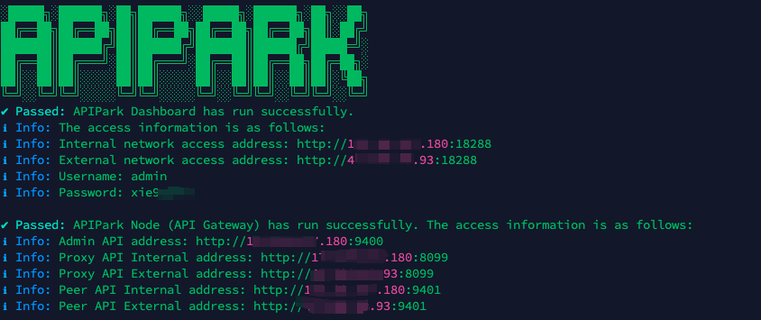
In my experience, you can see the successful deployment interface within 5 to 10 minutes. Then, you can log in to APIPark using your account.
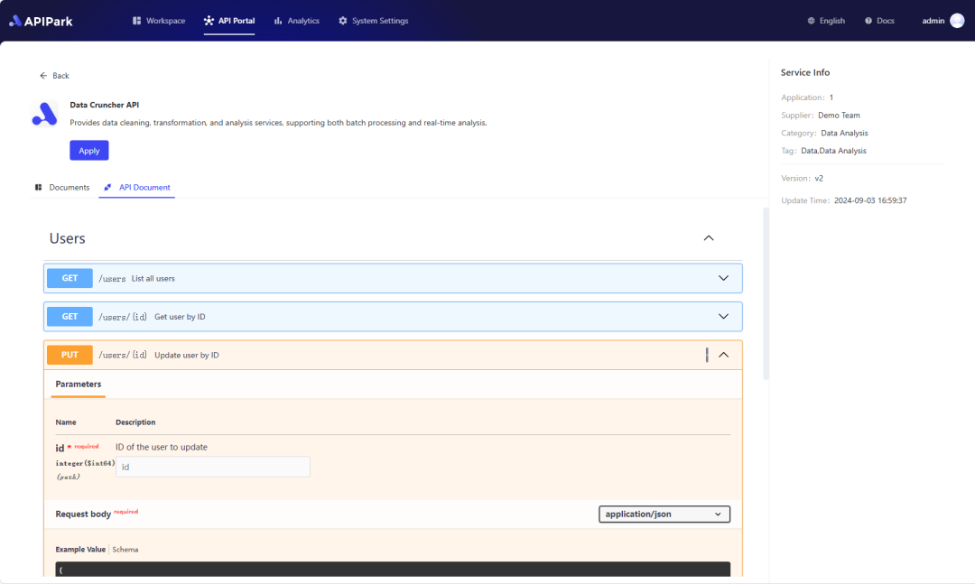
Step 2: Call the OpenAI API.