Your Guide to Breakers: Types, Safety, and Selection
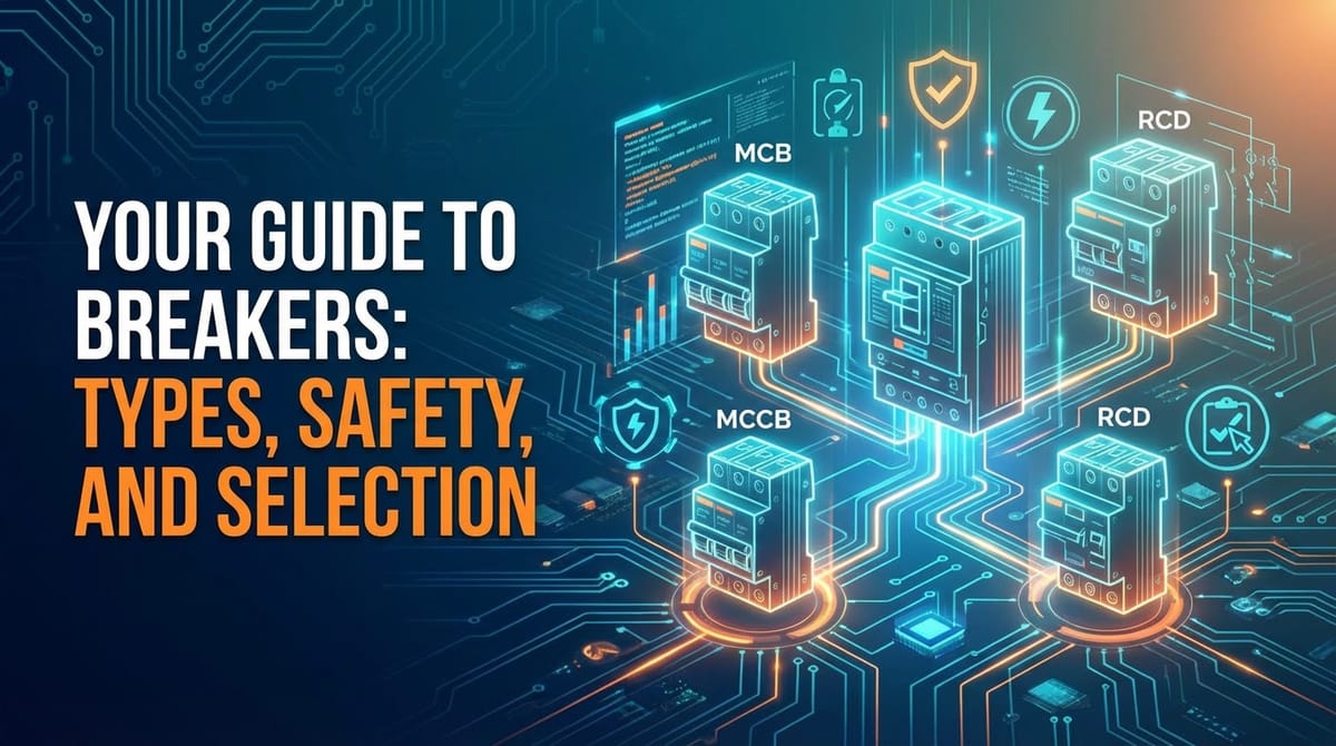


I. Introduction: The Unsung Guardians of Our Electrical World
In the intricate tapestry of modern life, electricity powers our homes, industries, and technological advancements, weaving itself into the very fabric of our existence. Yet, this ubiquitous force, while indispensable, harbors inherent dangers. Uncontrolled electrical currents can lead to catastrophic consequences – fires, electrocutions, equipment damage, and widespread power outages. It is precisely to mitigate these risks that circuit breakers, often inconspicuous and rarely appreciated until a fault occurs, stand as the frontline guardians of our electrical safety. These ingenious devices are more than mere on/off switches; they are sophisticated safety mechanisms designed to automatically interrupt the flow of electricity when an anomaly, such as an overload or a short circuit, is detected, thereby protecting both human lives and valuable assets.
The journey of circuit protection from rudimentary fuses to the highly advanced, "smart" breakers of today is a testament to persistent human innovation in the face of evolving electrical demands. Early electrical systems relied heavily on simple fuse wires, which, while effective at breaking a circuit, were a one-time use solution, requiring replacement after each event. The development of the reusable circuit breaker marked a significant leap forward, offering convenience, enhanced safety, and greater reliability. Over the decades, as electrical loads grew exponentially and the understanding of various fault conditions deepened, so too did the complexity and specialization of circuit breakers. From miniature breakers safeguarding individual household appliances to massive industrial breakers protecting entire power grids, their fundamental mission remains the same: to act as an immediate, automatic failsafe, preventing minor electrical glitches from escalating into major disasters.
This comprehensive guide aims to illuminate the multifaceted world of circuit breakers, delving into their diverse types, the critical safety protocols associated with their use, and the meticulous considerations involved in their selection. We will embark on a detailed exploration of the underlying principles that govern their operation, dissecting the internal mechanisms that allow them to detect and respond to various electrical faults. Furthermore, we will underscore the paramount importance of safety, outlining the essential practices and personal protective equipment necessary when working with or around these vital components. Finally, we will equip you with the knowledge required to make informed decisions when selecting the appropriate breaker for specific applications, ensuring not only compliance with regulatory standards but also the highest degree of protection and operational efficiency for your electrical systems. Understanding these silent sentinels is not merely an academic exercise; it is an essential step towards fostering a safer, more resilient electrical environment for everyone.
II. The Fundamental Principles of Circuit Protection
To truly appreciate the engineering marvel that is the circuit breaker, one must first grasp the fundamental electrical phenomena they are designed to counteract. Electricity, in its controlled flow, is a boon; in its uncontrolled state, it becomes a formidable hazard. Circuit protection, therefore, is not a luxury but an absolute necessity, serving as the cornerstone of any safe and reliable electrical installation.
A. Why Do We Need Protection? Understanding Electrical Faults
The primary reasons for circuit protection stem from the inherent risks associated with three main types of electrical faults: overcurrents, short circuits, and ground faults. Each presents a distinct threat and necessitates a specific protective response.
1. Overcurrent: An overcurrent occurs when the amount of electrical current flowing through a circuit exceeds the circuit's design limits. This can happen for several reasons. One common scenario is an overload, where too many appliances or devices are plugged into a single circuit, collectively demanding more current than the wiring can safely handle. Imagine a garden hose designed for a gentle flow suddenly being forced to accommodate the output of a fire hydrant; the hose cannot cope. Similarly, electrical conductors, when subjected to current beyond their rated capacity, begin to heat up significantly. This excessive heat can degrade the insulation around the wires, leading to a breakdown that could eventually cause a short circuit or even ignite surrounding combustible materials, culminating in an electrical fire. The rate of heat generation is proportional to the square of the current (I²R losses), meaning even a modest increase in current can lead to a substantial rise in temperature, posing a serious fire risk over time.
2. Short Circuit: A short circuit is arguably the most dangerous and dramatic electrical fault. It occurs when an unintended, low-resistance path is created between two conductors with different potentials (e.g., live and neutral, or live and ground). This low-resistance path bypasses the normal load of the circuit, allowing an enormous surge of current to flow almost instantaneously, often thousands of times greater than the normal operating current. Think of a river suddenly finding a direct, steep path to the ocean, bypassing all the winding bends and obstacles; the flow becomes torrential. This sudden, massive surge of current generates an immense amount of heat and electromagnetic force in a very short period. The consequences can be devastating: violent arcing, explosions, melting of conductors, and immediate ignition of flammable materials. A short circuit demands an almost instantaneous response from the protective device to prevent widespread destruction and severe injury.
3. Ground Fault: A ground fault, also known as an earth fault, occurs when current inadvertently flows to the ground or to an unintended metallic path that is connected to ground. This typically happens when insulation fails, and a live conductor touches a grounded metal casing of an appliance, a water pipe, or even a person who is simultaneously in contact with the ground. While a ground fault might not always result in a massive current surge like a short circuit, it presents a direct and extremely lethal electrocution hazard. If a person becomes part of this unintended path to ground, even a relatively small amount of current (as little as 50 milliamperes) can cause ventricular fibrillation and death. Traditional overcurrent protection (like standard breakers) may not trip fast enough or at low enough current levels to protect against ground faults, as the fault current might be less than the breaker's trip rating. This highlights the need for specialized ground fault protection devices.
B. The Basic Function of a Breaker: Detection and Interruption
At its core, a circuit breaker performs two critical functions: detection and interruption.
1. Detection: The breaker continuously monitors the current flowing through the circuit it protects. When the current deviates from predefined safe parameters, its internal mechanisms are triggered. This detection process is highly sophisticated and can involve thermal, magnetic, or electronic means, depending on the type of fault and the breaker's design. For overloads, the detection might be a gradual heating of a bimetallic strip; for short circuits, it might be the rapid generation of an electromagnetic field; and for ground faults, it involves sensing an imbalance in current between live and neutral conductors.
2. Interruption: Once a fault is detected, the breaker's primary objective is to swiftly and safely interrupt the flow of current. This is achieved by physically opening a set of contacts within the breaker. The challenge lies in safely extinguishing the electrical arc that forms when these contacts separate under load. An arc is a superheated plasma that can sustain current flow even after the contacts have physically parted, potentially leading to continued fault current and damage. Breakers employ various arc suppression techniques, such as arc chutes (metal plates that cool and lengthen the arc), vacuum interrupters, or pressurized gases, to rapidly extinguish this arc and fully isolate the faulty section of the circuit. The speed and effectiveness of this interruption are paramount in minimizing damage and ensuring safety.
C. Key Operational Concepts: Trip Curves and Interrupting Rating
Two critical concepts define a breaker's operational characteristics and suitability for specific applications: trip curves and interrupting rating.
1. Trip Curves (Time-Current Characteristics): A trip curve is a graphical representation that illustrates the relationship between the magnitude of an overcurrent and the time it takes for the breaker to trip and interrupt the circuit. These curves are not simple lines but rather zones, reflecting the inherent tolerances in manufacturing and operation.
- Long-Time Delay: This portion of the curve handles overloads. The breaker is designed to carry its rated current continuously without tripping. For slight overloads (e.g., 125% of rated current), it will trip after a certain delay (e.g., several minutes). For higher overloads (e.g., 200%), it will trip much faster (e.g., a few seconds). This delay is crucial to allow for normal, temporary current surges, such as the inrush current when starting a motor, without nuisance tripping. This protection is typically provided by a thermal element.
- Short-Time Delay: Some larger breakers incorporate a short-time delay for intermediate fault currents, often associated with motor starting or transformer energization, which are higher than normal operational currents but not full-blown short circuits. This feature allows for coordination with downstream protective devices, ensuring that only the faulty section is isolated.
- Instantaneous Trip: This part of the curve represents the breaker's response to very high currents, characteristic of short circuits. At a certain multiple of the rated current (e.g., 5 to 10 times for a common MCB), the breaker will trip almost instantaneously (typically within milliseconds). This rapid response is critical to limit the energy let-through during a severe fault, minimizing damage. This protection is typically provided by a magnetic element.
Understanding trip curves is vital for selectivity (or coordination), which ensures that only the protective device immediately upstream of a fault trips, leaving healthy parts of the system operational. Proper coordination prevents a minor fault from cascading into a widespread outage.
2. Interrupting Rating (kAIC - kiloAmperes Interrupting Capacity): The interrupting rating, also known as the short-circuit current rating (SCCR), specifies the maximum short-circuit current that a circuit breaker can safely interrupt without sustaining damage to itself and without endangering personnel. This rating is expressed in kiloamperes (kA). When a short circuit occurs, the fault current can be massive, far exceeding the breaker's normal operating current. If the fault current flowing through the breaker exceeds its interrupting rating, the breaker may fail catastrophically – contacts could weld shut, the casing could explode, or it could simply fail to clear the fault, leading to severe damage to the electrical system and potential injury.
It is absolutely crucial that the interrupting rating of a breaker is equal to or greater than the maximum available short-circuit current at its point of installation. The available short-circuit current is determined by the characteristics of the upstream power source (e.g., utility transformer capacity, feeder impedance). Incorrectly sizing a breaker's interrupting rating can turn a protective device into a liability during a severe fault.
By meticulously understanding these principles – the nature of electrical faults, the two-fold function of detection and interruption, and the critical operational parameters of trip curves and interrupting ratings – we lay the groundwork for a detailed exploration of the myriad types of circuit breakers available and the judicious considerations involved in their safe and effective selection.
III. A Deep Dive into Breaker Types: Categorization and Functionality
The world of circuit breakers is incredibly diverse, with devices specifically engineered to meet the unique demands of various electrical environments, from the smallest residential circuit to the largest industrial power grid. Each type employs distinct mechanisms for detecting faults and interrupting current, tailored to the magnitude and nature of the electrical challenges it addresses.
A. Miniature Circuit Breakers (MCBs)
Miniature Circuit Breakers (MCBs) are the ubiquitous protectors found in most residential and light commercial electrical panels. Designed primarily for low-voltage applications (typically up to 240V or 415V) and lower current ratings (typically up to 125 A), MCBs are highly standardized and offer a convenient, resettable alternative to fuses. Their compact size belies a sophisticated internal mechanism that provides both overload and short-circuit protection.
1. Thermal Mechanism Explained
The thermal protection in an MCB primarily addresses overload conditions. It utilizes a bimetallic strip, which is a composite metal strip made of two different metals bonded together, each with a different coefficient of thermal expansion. When an overcurrent flows through the MCB, it generates heat. This heat causes the bimetallic strip to warm up. Because the two metals expand at different rates, the strip bends. The greater the current (and thus the heat), the more the strip bends. At a predetermined level of bending, the strip physically trips a latch mechanism, causing the contacts to open and interrupt the circuit. This mechanism has an inherent time delay: for a slight overload, it takes longer for the strip to heat sufficiently and bend, while for a larger overload, it heats and bends much faster. This time-delay characteristic is precisely what makes it suitable for protecting against sustained overloads without nuisance tripping from momentary current surges (like motor start-up).
2. Magnetic Mechanism Explained
The magnetic protection in an MCB is designed for rapid response to severe short-circuit conditions. It consists of an electromagnet (a coil of wire) placed in series with the main current path. When a short circuit occurs, an extremely high current flows through the coil almost instantaneously. This surge of current generates a powerful magnetic field around the coil. This magnetic field is strong enough to attract an armature (a small metal plunger) within the breaker, which in turn actuates a trip bar, causing the main contacts to open very quickly. Unlike the thermal mechanism, which has a time delay, the magnetic mechanism provides instantaneous tripping, typically within milliseconds, to minimize the damage caused by the massive energy release during a short circuit. The trip point for the magnetic element is usually set at a multiple (e.g., 5 to 10 times) of the breaker's rated current.
3. Thermal-Magnetic Operation
The genius of the MCB lies in its combined thermal-magnetic operation. It integrates both mechanisms to provide comprehensive protection against a wide range of fault currents. The thermal element handles sustained overloads with a time delay, while the magnetic element handles instantaneous short circuits. Both mechanisms work independently to trip the common contacts, ensuring that the circuit is protected effectively under various fault conditions. This dual functionality makes MCBs highly versatile and widely adopted for general circuit protection.
4. Applications and Limitations
MCBs are the workhorses of electrical protection in: * Residential Homes: Protecting lighting circuits, receptacle circuits, and small appliance circuits. * Light Commercial Buildings: Used for similar applications as residential, but often in larger quantities. * Small Industrial Panels: For controlling and protecting individual motors or auxiliary circuits.
Despite their widespread use, MCBs have limitations. Their current ratings typically max out around 125 A, and their interrupting ratings (kAIC) are generally lower (e.g., 6 kA or 10 kA), making them unsuitable for circuits with very high available short-circuit currents or for protecting large industrial machinery that draws hundreds or thousands of amperes. For these more demanding applications, more robust breaker types are required.
B. Molded Case Circuit Breakers (MCCBs)
Molded Case Circuit Breakers (MCCBs) represent a significant step up from MCBs in terms of current and voltage ratings, interrupting capacity, and application versatility. They are widely used in commercial, industrial, and larger residential installations where higher levels of protection and control are needed.
1. Construction and Higher Current Ratings
MCCBs derive their name from their integrally molded, robust insulating case, typically made of thermoset composite resins. This sturdy, non-vented case houses all the operational components, providing insulation and protection against environmental factors. MCCBs are available in a much broader range of current ratings than MCBs, typically from 10 A up to 2500 A, and for higher voltages (up to 600V AC). Their internal components, including larger contacts and more robust arc chutes, are designed to handle and safely interrupt the higher fault currents associated with larger electrical systems. They also feature greater physical endurance to withstand the mechanical stresses during fault interruptions.
2. Adjustable Trip Units
One of the key distinguishing features of many MCCBs, especially those with higher current ratings, is the presence of adjustable trip units. Unlike MCBs with fixed trip characteristics, MCCBs can often be customized to precisely match the load and coordination requirements of a specific circuit. These trip units can be: * Thermal-Magnetic Trip Units: Similar in principle to MCBs but more robust. Many larger MCCBs offer adjustable thermal (long-time delay) and magnetic (instantaneous) trip settings. This allows engineers to fine-tune the overload protection and short-circuit response. * Electronic Trip Units: Modern MCCBs frequently incorporate advanced electronic trip units, which utilize microprocessors to sense current and initiate tripping. These units offer much greater flexibility and precision in adjusting trip characteristics, including: * Long-Time Delay: Adjustable current settings for overload protection (e.g., 0.5 to 1 times the sensor rating). * Short-Time Delay: Adjustable current magnitude and time delay for intermediate fault currents, crucial for selective coordination. * Instantaneous Trip: Adjustable threshold for rapid short-circuit protection. * Ground Fault Protection: Many electronic trip units include integrated ground fault protection, sensing current imbalances and tripping at low current levels to protect against electric shock hazards. * Zone Selective Interlocking (ZSI): A communication feature allowing breakers to coordinate tripping times, ensuring that the breaker closest to the fault trips first, even with very short time delays.
The adjustability of these trip units makes MCCBs ideal for complex distribution systems where selective coordination between multiple protective devices is critical to minimize power outages.
3. Industrial and Commercial Applications
MCCBs are indispensable in a wide array of demanding applications: * Main Service Entrance: As the primary disconnect and overcurrent protection for entire buildings. * Feeder Circuits: Protecting distribution panels and large branches throughout a facility. * Motor Control Centers (MCCs): Protecting large motors and their control circuits. * Industrial Machinery: Providing protection for heavy equipment and production lines. * Data Centers: Ensuring reliable power distribution to critical IT infrastructure. * Commercial Building Distribution: Used in switchboards and panelboards to protect various loads.
Their robustness, higher ratings, and customizable trip characteristics make MCCBs a cornerstone of reliable and safe electrical distribution in medium to large-scale applications.
C. Air Circuit Breakers (ACBs)
Air Circuit Breakers (ACBs) are a class of low-voltage (typically up to 1000V) power circuit breakers characterized by their use of ambient air as the arc-quenching medium. They are designed for very high current applications and high interrupting capacities, typically ranging from 800 A to 6300 A (and even higher in some specialized cases), making them suitable for main power distribution points in large industrial and commercial facilities.
1. High Current, Low Voltage Applications
ACBs are predominantly found in switchgear for main incomers, bus couplers, and large feeder circuits within industrial plants, large commercial buildings, power stations, and other heavy-duty electrical systems. Their robust construction allows them to safely handle very high continuous currents and interrupt extremely large short-circuit currents, often exceeding 100 kA. Unlike MCCBs, ACBs are typically "draw-out" type, meaning their main assembly can be easily withdrawn from the switchgear cubicle for maintenance or replacement without disturbing the main busbars, a critical feature for minimizing downtime in industrial environments.
2. Arc Extinguishing Principle
The defining characteristic of ACBs is their method of arc suppression, which relies on the properties of air. When the contacts open under fault conditions, an electrical arc forms between them. To extinguish this arc, ACBs employ a combination of techniques: * Arc Chutes: The contacts are situated within complex structures called arc chutes. These chutes are typically made of insulating material with multiple metal plates or fins. As the arc is drawn into the chute, it is rapidly lengthened, cooled, and divided into a series of smaller, less energetic arcs by the metal plates. This process increases the arc's resistance, eventually extinguishing it. * Magnetic Blowout: In some designs, a magnetic field is used to "blow" the arc into the arc chute more quickly, further aiding in its extinction. * Pneumatic Force: The mechanical force of the contacts opening can also create a blast of air that helps to extinguish the arc.
The design of the arc chute is critical; it must be capable of dissipating the enormous energy of the arc without failing, ensuring the breaker can repeatedly perform its function.
3. Maintenance and Advantages
ACBs are known for their ruggedness and extended operational life, often exceeding 20-30 years with proper maintenance. Key advantages include: * High Interrupting Capacity: Capable of safely clearing very high short-circuit currents. * Selective Coordination: Advanced electronic trip units, often with ZSI, ensure precise coordination. * Maintainability: Their draw-out design facilitates easier inspection, cleaning, and replacement of parts (like contacts or arc chutes), reducing long-term operational costs. * Flexibility: Adjustable electronic trip units offer extensive customization for protection characteristics.
Due to their large size, weight, and complexity, ACBs require periodic professional maintenance to ensure their continued reliability and performance. This typically involves cleaning, contact inspection, lubrication, and testing of the trip unit.
D. Vacuum Circuit Breakers (VCBs)
Vacuum Circuit Breakers (VCBs) represent a superior technology for medium-voltage applications, typically ranging from 1 kV to 38 kV, where they have largely replaced oil and air blast breakers. Their core innovation lies in the use of a vacuum interrupter to extinguish the electrical arc.
1. Medium Voltage Applications
VCBs are predominantly used in: * Utility Distribution Networks: For protecting feeders and transformers in substations. * Industrial Plants: Especially those with large motor loads, arc furnaces, or other high-power equipment. * Power Generation Facilities: For switchgear protecting generators and auxiliary systems. * Transmission Substations (occasionally): Though SF6 breakers are more common for very high voltage transmission.
Their compact size and high reliability make them a preferred choice for medium-voltage switchgear.
2. Arc Extinguishing in Vacuum
The heart of a VCB is the vacuum interrupter, a sealed ceramic or glass envelope containing fixed and moving contacts within a high vacuum (typically less than 10⁻⁴ Torr). The principle of arc quenching in a vacuum is fundamentally different from air. When the contacts open in a vacuum, the absence of an ionized medium means that the arc cannot sustain itself for long. The high dielectric strength of the vacuum ensures that the arc collapses rapidly at the first current zero crossing. Furthermore, the metal vapor created by the arc rapidly condenses on the surrounding contact material and shields, preventing re-ignition. This process is incredibly efficient and results in: * Very Fast Arc Extinction: Typically within half a cycle of the AC waveform. * Minimal Arc Energy: Less heat and light are produced compared to other technologies. * No Exhaust Gases: As there's no air or gas involved, there are no harmful byproducts or explosive gases to vent.
3. Advantages in Performance and Lifespan
VCBs offer several compelling advantages: * High Reliability and Long Life: The sealed vacuum interrupter prevents contamination and corrosion of the contacts, leading to minimal wear and tear and a very long operational life (often 20,000 to 30,000 operations). * Low Maintenance: Due to the sealed contacts and absence of arc byproducts, VCBs require significantly less maintenance than air or oil breakers. * Compact Size: The vacuum interrupter is small, allowing for more compact switchgear designs. * Environmental Friendliness: No use of harmful gases (like SF6) or oil, making them a greener option. * High Interrupting Capacity: Capable of interrupting very high fault currents.
The main limitation is that VCBs are generally not used for very low voltages (where MCBs/MCCBs are sufficient) or for extremely high transmission voltages (where SF6 becomes more advantageous).
E. SF6 Circuit Breakers (SF6 CBs)
Sulfur Hexafluoride (SF6) Circuit Breakers are predominantly used in high and extra-high voltage transmission and distribution systems, typically from 33 kV up to 800 kV and beyond. SF6 gas is a synthetic, non-toxic, non-flammable, and extremely stable gas with exceptional dielectric and arc-quenching properties, making it an ideal medium for high-voltage fault interruption.
1. High Voltage Applications
SF6 CBs are critical components in: * High Voltage Substations: For protecting transmission lines, transformers, and busbars. * Power Generation Plants: As generator circuit breakers for very large generators. * Heavy Industrial Installations: Where very high voltage power is distributed.
They are designed to handle the immense voltages and fault currents encountered in national and international power grids.
2. Sulfur Hexafluoride Properties for Arc Quenching
The remarkable arc-quenching ability of SF6 gas stems from several properties: * High Dielectric Strength: SF6 gas has a dielectric strength three times higher than air at atmospheric pressure, meaning it can withstand much higher voltages without breaking down. This allows for smaller clearances between live parts. * Excellent Heat Transfer: SF6 is very good at absorbing heat from the arc. * Electronegativity: SF6 molecules are highly electronegative, meaning they readily absorb free electrons from the arc plasma, converting them into heavy negative ions that are poor current carriers. This rapidly deionizes the arc path and restores the dielectric strength of the gap between the contacts, leading to very effective arc extinction. * Self-Healing: After the arc is extinguished, the SF6 molecules recombine to their original state, making the gas reusable.
The arc quenching methods typically involve either a puffer type mechanism (where a piston compresses SF6 gas and blasts it into the arc) or a self-blast type mechanism (where the arc's own energy heats and pressurizes the SF6 gas, which then acts to extinguish the arc).
3. Environmental Considerations and Handling
While SF6 offers unparalleled performance for high-voltage applications, it is a potent greenhouse gas, with a global warming potential (GWP) approximately 23,500 times higher than CO2 over a 100-year period. It is also an extremely long-lived gas in the atmosphere, persisting for thousands of years. Due to these environmental concerns: * Strict Regulations: The handling, use, and disposal of SF6 gas are heavily regulated worldwide to prevent leakage into the atmosphere. * Closed Systems: SF6 CBs are designed as sealed-for-life or very low-leakage systems. * Recycling and Recovery: When SF6 equipment reaches the end of its life, the gas must be carefully recovered and recycled, not released. * Alternative Research: Significant research is ongoing to find environmentally friendly alternatives to SF6 gas, though none currently match its combined performance for very high voltage applications.
Despite environmental challenges, SF6 breakers remain the dominant technology for critical high-voltage transmission due to their reliability, compact design, and exceptional interrupting capability.
F. Residual Current Devices (RCDs) / Ground Fault Circuit Interrupters (GFCIs)
While MCBs and MCCBs protect against overcurrents (overloads and short circuits), they are generally not sensitive enough to detect and respond to low-level ground faults that can be lethal to humans. This is where Residual Current Devices (RCDs), known as Ground Fault Circuit Interrupters (GFCIs) in North America, become indispensable. Their primary purpose is to protect people from electric shock by quickly disconnecting the power when a ground fault is detected.
1. Principle of Operation (Current Imbalance)
RCDs/GFCIs operate on the principle of current balance. In a healthy circuit, the current flowing out on the "live" (or "hot") conductor should be exactly equal to the current flowing back on the "neutral" conductor. An RCD/GFCI has a differential current transformer (also called a core balance transformer) that continuously monitors these two currents. * Normal Operation: The magnetic fields created by the outgoing and incoming currents cancel each other out in the core balance transformer, resulting in zero net flux. * Ground Fault: If there is a ground fault (e.g., a person touches a live wire and current flows through their body to ground), some of the current bypasses the neutral conductor and flows to ground. This creates an imbalance in the currents flowing through the core balance transformer. The outgoing current is now greater than the incoming current. This imbalance creates a net magnetic flux in the transformer, which induces a small current in a sensing coil. * Tripping: When the induced current reaches a predetermined threshold (typically 30 mA in RCDs and 5 mA in GFCIs for personnel protection), it activates a tripping mechanism, which rapidly opens the main contacts and interrupts the circuit. This interruption occurs within milliseconds (typically 25-40 ms), fast enough to prevent ventricular fibrillation and save a life.
It's crucial to understand that an RCD/GFCI does not protect against overloads or short circuits (unless the fault current is also a ground fault). It specifically targets ground faults that pose a direct shock hazard.
2. Protection Against Electric Shock
RCDs/GFCIs are specifically mandated in locations where there is an increased risk of electric shock due to the presence of water or grounded surfaces. These include: * Bathrooms and Kitchens: Sinks, wet floors, and appliances increase the risk. * Outdoor Outlets: Exposure to rain, dampness, and earth contact. * Garages and Basements: Often damp and can have grounded concrete floors. * Swimming Pool Areas: For pumps, lighting, and other equipment near water. * Construction Sites: High risk of damaged cables and exposure to ground.
In North America, 5 mA GFCIs are designed for human personnel protection. In many other parts of the world, 30 mA RCDs are common for similar purposes, while 10 mA RCDs are sometimes used in particularly sensitive areas or for hospital applications. Higher rating RCDs (e.g., 100 mA, 300 mA) are often used for equipment protection or as main incomers in commercial settings for fire protection, as a large ground fault can also be a fire hazard.
3. Testing and Common Misconceptions
Every RCD/GFCI should have a "Test" button. Pressing this button creates a simulated ground fault internally, which should cause the device to trip. This test should be performed monthly to ensure the device is functioning correctly.
Common misconceptions include: * RCDs/GFCIs protect against all electrical hazards: They only protect against ground faults that could lead to electric shock or certain types of fires. They do not protect against line-to-line short circuits or overloads. * Tripping means a faulty device: Tripping indicates a fault on the circuit, not necessarily a faulty RCD/GFCI (though a faulty RCD/GFCI can occur). It means the device is doing its job. * They prevent all fires: While they can prevent fires caused by ground faults, they do not detect arc faults (arc fault circuit interrupters do this) or fires caused by severe overloads without a ground path.
G. Arc Fault Circuit Interrupters (AFCIs)
Arc Fault Circuit Interrupters (AFCIs) are another crucial safety device, designed to protect against a different, insidious type of electrical hazard: arc faults. Arc faults are unintended electrical arcs in wiring that can generate significant heat and ignite surrounding insulation or materials, leading to electrical fires. These faults are often not detected by traditional overcurrent protection (MCBs) or GFCIs.
1. Detecting Dangerous Arcs
Arc faults can occur in various ways: * Series Arc Faults: Occur when a conductor breaks or becomes severely damaged, creating a gap in the series path. Current still flows but with intermittent arcing. Examples include a loose connection, a damaged appliance cord, or a nail piercing a wire. * Parallel Arc Faults: Occur when insulation between two conductors (e.g., live and neutral, or live and ground) breaks down, creating an arc between them without a direct, low-resistance short circuit path. This can be caused by pinched wires, damaged insulation, or rodents chewing through wires.
Traditional breakers are often slow to respond or completely blind to arc faults because the fault current might not be high enough to trip an MCB (especially for series arcs) and might not involve a ground path (thus bypassing GFCI detection). AFCIs, on the other hand, employ sophisticated digital signal processing and advanced algorithms to continuously monitor the current waveform for specific "signatures" or patterns that indicate the presence of dangerous arcing. These patterns are distinct from the normal electrical noise generated by appliances (like motors starting).
2. Series and Parallel Arc Detection
Modern AFCIs are designed to detect both series and parallel arc faults. * Series Arc Detection: Identifies abnormal current fluctuations and disruptions in the series path. * Parallel Arc Detection: Recognizes the irregular, high-frequency noise and sudden current surges characteristic of arcs between conductors.
When an AFCI detects these specific arc fault patterns, it rapidly trips the circuit, interrupting the power before the arc can generate enough heat to start a fire.
3. Complementary Protection with GFCIs
AFCIs are primarily designed for fire protection, particularly in bedroom areas where many appliances and cords are used, and in living areas. They are mandated in many residential codes (e.g., National Electrical Code in the US) for bedrooms and increasingly for other living spaces.
It's important to understand that AFCIs and GFCIs protect against different types of hazards: * AFCI: Primarily protects against fires caused by arcing. * GFCI: Primarily protects against electric shock caused by ground faults.
Neither device inherently replaces the other; they offer complementary protection. A circuit can have an arc fault that isn't a ground fault, and it can have a ground fault that isn't an arc fault (or at least not a sustained, fire-starting one). Therefore, for comprehensive safety, both types of protection may be necessary in certain locations.
H. Dual Function Circuit Breakers (GFCI/AFCI Combination)
Recognizing the need for both ground fault and arc fault protection in many residential circuits, manufacturers developed Dual Function Circuit Breakers. These innovative devices combine the protective capabilities of both a GFCI and an AFCI into a single unit, fitting into a standard circuit breaker slot in the electrical panel.
1. The Ultimate in Residential Protection
Dual function breakers offer the most comprehensive residential circuit protection available from a single device. They simultaneously guard against: * Overloads: Standard thermal protection. * Short Circuits: Standard magnetic protection. * Ground Faults: Protection against electric shock (5 mA trip level). * Arc Faults: Protection against fires caused by both series and parallel arcs.
This "all-in-one" solution simplifies installation compared to installing separate GFCI and AFCI devices on a single circuit. It reduces panel clutter and ensures that the protected circuit benefits from the highest level of safety. These breakers are typically required for all new and renovated residential branch circuits by current electrical codes in many regions, especially where both AFCI and GFCI protection are mandated.
2. Wiring and Installation Nuances
Installing dual function breakers requires careful attention to wiring, particularly the neutral connection. Unlike standard MCBs that only connect to the hot wire, GFCIs and AFCIs (and thus dual function breakers) require a dedicated neutral connection back to the breaker itself. * The circuit's hot (black) wire connects to the line terminal on the breaker. * The circuit's neutral (white) wire connects to a dedicated terminal on the breaker, and a short white pigtail from the breaker connects to the neutral busbar in the panel. * The load neutral wire (from the circuit going out to receptacles/lights) must be connected to the load neutral terminal on the breaker, not directly to the panel's neutral busbar. If the load neutral is mistakenly connected to the panel's neutral bus, the breaker will nuisance trip due to an imbalance.
Proper installation is critical for the correct operation of dual function breakers, ensuring they can effectively monitor and protect against all specified fault conditions.
I. Specialized Breakers (e.g., Insulated Case, Fusible, DC Breakers)
Beyond the commonly encountered AC breakers discussed, there are several specialized types designed for niche applications:
- Insulated Case Circuit Breakers (ICCBs): These are essentially a hybrid between MCCBs and ACBs. They typically have higher continuous current ratings and interrupting capacities than standard MCCBs but use an insulated case similar to an MCCB. They often feature sophisticated electronic trip units and are designed for heavy-duty commercial and industrial applications where maintenance and coordination are important, but the full robustness and draw-out features of an ACB might not be strictly necessary. They bridge the gap between large MCCBs and small ACBs.
- Fusible Circuit Breakers: These are circuit breakers that also integrate a fuse, often as a backup or to provide extremely high interrupting capacities where needed. The breaker mechanism handles most fault conditions, but if a very severe short circuit occurs beyond the breaker's interrupting rating, the integrated fuse will blow, providing ultimate protection. These are less common today but were used in older systems or very high short circuit current environments.
- DC Circuit Breakers: Unlike AC circuits, which have natural current zero crossings that aid in arc extinction, DC circuits maintain a constant current flow. This makes interrupting a DC arc much more challenging, as it requires physically lengthening the arc and rapidly dissipating its energy without the benefit of a current zero. DC breakers are specialized devices used in applications like battery systems, solar power installations, uninterruptible power supplies (UPS), and electric vehicle charging infrastructure. Their design incorporates powerful magnetic blowouts and special arc chutes to force and extinguish the persistent DC arc. They are rated based on DC voltage and current, and their interrupting capacity is specific to DC fault conditions.
- Miniature DC Breakers: Similar to AC MCBs but designed for DC voltages (e.g., 12V, 24V, 48V, up to several hundred volts DC), often used in automotive, marine, and small-scale solar systems.
- Solid State Circuit Breakers (SSCBs): An emerging technology, SSCBs use power electronics (like IGBTs or SCRs) instead of mechanical contacts to interrupt current. They offer extremely fast clearing times (microseconds), highly precise trip characteristics, and no moving parts. While currently more expensive and complex, they hold immense promise for critical applications requiring ultra-fast protection, such as data centers, microgrids, and highly sensitive industrial processes. Their ability to switch on and off without arcing also reduces wear and tear.
This exploration of breaker types underscores the intricate engineering behind circuit protection, where each device is a finely tuned instrument designed to address specific electrical challenges, ensuring the safety and reliability of our diverse electrical systems.
IV. Comprehensive Safety Protocols and Best Practices
Working with electricity, especially with devices as critical as circuit breakers, demands an unwavering commitment to safety. Disregarding established safety protocols can lead to severe injury, fatality, or extensive property damage. Understanding the hazards and adhering to best practices is not merely a recommendation; it is a professional and moral imperative.
A. Understanding Electrical Hazards: More Than Just a Shock
Electrical hazards are multifaceted and insidious, often capable of causing harm without direct contact or visible cues. It is crucial to recognize the distinct dangers beyond a simple electric shock.
1. Electrocution and Shock: This is the most commonly understood electrical hazard. An electric shock occurs when a person becomes part of an electrical circuit, allowing current to flow through their body. The severity of the shock depends on the path the current takes through the body, the amount of current, and the duration of contact. Even relatively low currents (e.g., 50 mA) can cause ventricular fibrillation (a chaotic heart rhythm), leading to death (electrocution). Higher currents can cause severe burns, muscle contractions (which can prevent a person from letting go of the conductor), respiratory arrest, and damage to internal organs. The human body's resistance can vary widely, meaning a seemingly innocuous voltage can still be lethal under certain conditions (e.g., wet skin).
2. Arc Flash: An arc flash is a sudden, explosive release of electrical energy that occurs when an electrical current leaves its intended path and travels through the air from one conductor to another, or to ground. This event is often triggered by insulation failure, dropping a tool, or even opening an energized panel. The resulting arc creates an incredibly intense burst of heat (up to 35,000°F or 19,400°C – hotter than the sun's surface), blinding light (UV and infrared), and a powerful pressure wave (arc blast).
3. Arc Blast: The arc blast is a superheated, rapidly expanding plasma and vaporized metal that accompanies an arc flash. It creates a violent pressure wave that can throw workers across a room, rupture eardrums, collapse lungs, and propel molten metal shrapnel at incredibly high speeds. The force can be comparable to a small explosion.
4. Consequence of Inadequate Protection: Failure to implement proper electrical protection (e.g., undersized breakers, incorrect trip settings, missing GFCI/AFCI protection) or to follow safety procedures can exacerbate these hazards, turning a preventable incident into a catastrophe. Inadequate protection means a fault will not be cleared quickly or at all, allowing hazards to persist and escalate.
B. Lockout/Tagout (LOTO) Procedures: The Golden Rule of Electrical Safety
The Lockout/Tagout (LOTO) procedure is, without exaggeration, the single most critical safety protocol for any work involving electrical circuits and equipment. It is designed to prevent accidental energization of machinery or circuits during maintenance, repair, or servicing activities.
1. The Golden Rule of Electrical Safety
The fundamental principle of LOTO is to ensure that all hazardous energy sources – electrical, mechanical, hydraulic, pneumatic, thermal, chemical, etc. – are de-energized and locked/tagged out before work begins, and remain in that state until work is complete. For electrical systems, this means: * De-energization: The circuit breaker controlling the equipment or circuit must be switched to the "OFF" position. * Verification: The circuit must be tested with a properly functioning voltage tester to confirm it is indeed de-energized. * Isolation: A lock (padlock) must be applied to the breaker handle or disconnect switch, preventing it from being accidentally switched back on. * Tagging: A tag must be attached to the lock, indicating who applied the lock, the reason for the lockout, and the date/time.
2. Steps and Importance
A typical LOTO procedure for electrical work involves: 1. Preparation for Shutdown: Identify the energy source(s) and notify affected personnel. 2. Equipment Shutdown: Follow documented shutdown procedures. 3. Equipment Isolation: Operate the disconnect switch or circuit breaker to isolate the energy. 4. Application of Lockout/Tagout Devices: Apply personal locks and tags to the isolating device(s). Each worker involved should apply their own lock. 5. Verification of Zero Energy State: Crucially, test the circuit to ensure it is de-energized. This should involve a "test-before-touch" method: test the voltage tester on a known live source, then test the de-energized circuit, then re-test the voltage tester on the live source to confirm it's still working. 6. Performing the Work: Proceed with the maintenance or repair. 7. Removal of Lockout/Tagout Devices: Only the person who applied the lock may remove it, once the work is complete, tools are removed, and personnel are clear. 8. Equipment Re-energization: Follow proper start-up procedures.
The importance of LOTO cannot be overstated. It is the primary defense against unexpected energization, protecting workers from electrocution, arc flash, and other electrical injuries. Any deviation from LOTO procedures is a critical safety violation.
C. Personal Protective Equipment (PPE): Your Last Line of Defense
While LOTO prevents exposure to live energy, circumstances sometimes require working on or near energized electrical equipment (e.g., troubleshooting, voltage testing, hot tapping). In such cases, Personal Protective Equipment (PPE) becomes the vital last line of defense against the hazards of arc flash and shock.
1. Arc-Rated Clothing, Gloves, Eye Protection
Selecting the correct PPE requires a thorough arc flash risk assessment, which determines the potential incident energy (in cal/cm²) at a given point in the electrical system and thus the required Arc Flash Personal Protective Equipment (AFPPE) category. * Arc-Rated (AR) Clothing: This includes shirts, pants, coveralls, and outer layers made from flame-resistant materials specifically designed to not ignite, melt, drip, or conduct electricity when exposed to an arc flash. The clothing is rated by its Arc Thermal Performance Value (ATPV) or Energy Breakopen Threshold (EBT), which indicates the amount of incident energy it can withstand. Layers of AR clothing increase protection. * Insulated Gloves: Rubber insulating gloves (rated for the voltage being worked on) with leather protector gloves worn over them are essential for shock protection. They must be regularly inspected and dielectrically tested. * Eye Protection: Safety glasses or goggles (often integrated into a face shield) are required for impact protection. An arc-rated face shield or hood is mandatory for arc flash protection, protecting the face and neck from intense heat and light. * Head Protection: An arc-rated hard hat is necessary, often integrated with the face shield or hood. * Foot Protection: Dielectric safety footwear, typically steel-toed boots, provides some insulation and protection against crushing injuries.
2. Selecting the Right PPE for the Task
The specific PPE required depends entirely on the assessed hazard level (e.g., arc flash category 1, 2, 3, or 4) and the voltage of the equipment being worked on. It is not a "one-size-fits-all" approach. * Minimum Requirements: Even for basic electrical tasks, non-melting natural fiber clothing (cotton, wool) is often a minimum, as synthetic clothing can melt onto the skin. * Higher Risk Tasks: For tasks with higher incident energy, a full arc flash suit (hood, jacket, pants) with appropriate rating is required. * Daily Wear: Many companies now mandate arc-rated clothing as daily wear for electrical workers, even when not actively performing high-risk tasks, as a precaution against unexpected events.
Regular training on PPE selection, inspection, use, and maintenance is critical. PPE must be worn correctly and be in good condition to provide effective protection.
D. Safe Work Practices: De-energizing, Testing, Grounding
Beyond LOTO and PPE, a range of safe work practices further reduces risks when interacting with electrical systems.
1. De-energizing First (if possible): The principle of "Work De-energized Unless Infeasible" is fundamental. Always attempt to de-energize and lock out a circuit before beginning work. If de-energization creates an even greater hazard or is truly impossible for the task (e.g., voltage testing), then specific energized work permits, arc flash analyses, and appropriate PPE are mandatory.
2. Testing for Absence of Voltage: As part of LOTO, verifying the absence of voltage is non-negotiable. This involves: * Using a properly rated and calibrated voltage tester. * Testing the tester on a known live circuit before and after testing the de-energized circuit. * Testing all phases and the neutral conductor against ground and against each other. * Considering capacitive discharge, especially in high-voltage equipment, which can briefly store a charge.
3. Temporary Protective Grounding (TPG): After de-energizing and verifying zero voltage, temporary protective grounds should be applied to high-voltage conductors to protect against accidental re-energization or induced voltage from adjacent live circuits. TPG creates a low-resistance path to ground, ensuring that if energy were to somehow be restored, it would immediately shunt to ground, tripping upstream protection, rather than endangering personnel. The grounds must be applied and removed using insulated tools and following a specific sequence (ground first, then remove last).
4. Avoiding Complacency: Perhaps the most insidious hazard is complacency. Familiarity with electrical work can lead to a relaxed attitude towards safety protocols. Regular safety briefings, refresher training, and a culture that prioritizes safety over speed are essential to counteract this. Every electrical task, no matter how routine, carries potential risks.
E. Maintenance and Inspection: Sustaining Protection
Circuit breakers, like any other critical equipment, require regular maintenance and inspection to ensure their continued reliability and effectiveness as protective devices. A neglected breaker can fail to trip when needed or, worse, fail catastrophically during a fault.
1. Regular Checks, Cleaning, Thermal Imaging: * Visual Inspections: Periodically inspect breakers and their panels for signs of overheating (discoloration, melting), loose connections, physical damage, rust, or dust accumulation. * Cleaning: Dust, dirt, and moisture can degrade insulation and interfere with breaker operation. Panels and breakers should be cleaned regularly by qualified personnel, ensuring power is de-energized first. * Thermal Imaging: Using an infrared camera (thermal imager) can reveal "hot spots" in electrical panels or at breaker terminals. These hot spots indicate loose connections, overloading, or internal breaker faults that generate excessive heat, often before they become visible to the naked eye. Thermal imaging is a powerful predictive maintenance tool.
2. Professional Servicing Schedules: * Operational Testing: For larger breakers (MCCBs, ACBs, VCBs, SF6 CBs), periodic operational testing is crucial. This involves manually tripping the breaker (if safe to do so) to ensure the mechanism operates freely. * Primary and Secondary Injection Testing: For critical breakers, specialized tests like primary current injection (passing a high current through the breaker to verify its trip curve) and secondary current injection (testing the electronic trip unit independently) are performed by qualified professionals using specialized equipment. These tests verify that the breaker's trip characteristics are within specifications and that the device will operate correctly under fault conditions. * Contact Resistance Tests: Measure the resistance across the breaker's main contacts to ensure they are making good contact and not overheating. * Insulation Resistance Tests: Verify the integrity of the breaker's internal insulation. * Manufacturer Recommendations: Always adhere to the manufacturer's recommended maintenance schedules and procedures for specific breaker types.
Investing in a robust maintenance program for circuit breakers is an investment in the overall safety, reliability, and longevity of the entire electrical system. It transforms reactive problem-solving into proactive hazard prevention.
APIPark is a high-performance AI gateway that allows you to securely access the most comprehensive LLM APIs globally on the APIPark platform, including OpenAI, Anthropic, Mistral, Llama2, Google Gemini, and more.Try APIPark now! 👇👇👇
V. The Art and Science of Breaker Selection
Selecting the correct circuit breaker for a given application is a critical engineering decision that significantly impacts the safety, reliability, and cost-effectiveness of an electrical system. It's not simply a matter of matching current ratings; it involves a meticulous evaluation of electrical parameters, application-specific needs, environmental conditions, regulatory requirements, and future considerations. A misselected breaker can lead to nuisance tripping, equipment damage, system failures, or, most critically, severe safety hazards.
A. Key Electrical Parameters: The Foundational Criteria
The initial step in breaker selection involves a thorough understanding and matching of the fundamental electrical characteristics of the circuit it will protect.
1. Voltage Rating: Matching System Voltage, Insulation Levels
The breaker's voltage rating specifies the maximum system voltage it can safely interrupt. This rating must be equal to or greater than the nominal system voltage (e.g., 120V, 240V, 480V, 600V, 13.8kV). * Insulation Withstand: Beyond merely interrupting the circuit, the breaker's internal insulation and the air gaps between its open contacts must be capable of withstanding the recovery voltage that immediately appears across the contacts after the arc is extinguished. If the system voltage exceeds the breaker's rating, the insulation might break down, or the arc might re-strike across the open contacts, failing to clear the fault. * AC vs. DC: It's vital to use AC-rated breakers for AC circuits and DC-rated breakers for DC circuits. As discussed earlier, interrupting a DC arc is much more challenging due to the absence of natural current zero crossings, requiring specialized DC breaker designs.
2. Current Rating (Ampacity): Continuous Current, Conductor Protection
The breaker's continuous current rating (ampacity) specifies the maximum current it can carry indefinitely without tripping. This rating must be carefully matched to the ampacity of the conductors it protects and the connected load. * Conductor Protection: The primary role of the current rating is to protect the wires (conductors) from overheating due to sustained overloads. The National Electrical Code (NEC) and other standards typically require the overcurrent protective device to be sized at or below the ampacity of the conductors, with specific allowances for continuous loads (e.g., typically 125% of the continuous load current). * Load Requirements: While protecting the conductor is paramount, the breaker's rating must also be sufficient to allow the normal operation of the connected load, including any momentary inrush currents (e.g., motor starting currents) that are within acceptable limits of the breaker's time-delay characteristics. * Standard Sizes: Breakers come in standard current ratings (e.g., 15 A, 20 A, 30 A, 50 A, 100 A, etc.). The chosen rating should be the smallest standard size that satisfies the conductor protection and load requirements.
3. Interrupting Rating (kAIC): Withstanding Short-Circuit Currents, Source Impedance
The Interrupting Rating (kAIC) is perhaps the most critical safety rating and often the most overlooked. It represents the maximum short-circuit current the breaker can safely interrupt without being destroyed or failing to clear the fault. * Available Short-Circuit Current: This value is determined by an electrical study that calculates the maximum fault current that could flow at the point of installation, considering the impedance of the utility transformer, feeder cables, and other upstream components. This available fault current must never exceed the breaker's interrupting rating. * Consequences of Under-rating: If a breaker's kAIC rating is less than the available fault current, it will fail catastrophically during a short circuit, potentially exploding, starting a fire, and leaving the fault uncleared, leading to severe damage upstream and downstream. * Series Ratings: In some applications, lower kAIC rated breakers can be used downstream of a higher kAIC rated main breaker if the combination has been tested and listed as a "series rated system." The upstream breaker provides the necessary interrupting capacity for severe faults. This can offer cost savings but must be engineered and installed strictly according to listing requirements.
4. Trip Curve Characteristics: Time-Current Curves, Coordination, Selectivity
As discussed in Section II, the trip curve (time-current characteristic) defines how quickly a breaker responds to different magnitudes of overcurrent. This is crucial for: * Coordination (Selectivity): In systems with multiple layers of protection (e.g., a main breaker feeding a sub-panel with branch circuit breakers), coordination ensures that only the breaker immediately upstream of a fault trips, isolating the faulty section and leaving the rest of the system operational. To achieve this, downstream breakers need to trip faster than upstream breakers for a given fault current. This requires careful analysis of the time-current curves of all protective devices in series. * Load Compatibility: The trip curve must also be compatible with the connected load. For example, motors have high inrush currents upon starting that are momentary overloads. A breaker with an instantaneous trip setting that is too low, or a thermal trip that is too fast, might nuisance trip during normal motor start-up. Breakers with "motor protection" characteristics have specific trip curves (e.g., D-curve or K-curve in IEC standards) designed to accommodate these inrush currents without tripping prematurely, while still providing rapid short-circuit protection.
B. Application-Specific Considerations: Tailoring Protection
The environment and nature of the electrical load profoundly influence breaker selection.
1. Residential: Simplicity, Cost-Effectiveness, GFCI/AFCI Integration
- Primary Needs: Overload, short circuit, ground fault (shock protection), and arc fault (fire protection).
- Typical Breakers: MCBs are standard. GFCIs are required for wet locations, and AFCIs (or dual function AFCI/GFCI breakers) are increasingly mandated for living areas and bedrooms.
- Focus: Ease of installation, cost-effectiveness, and basic safety compliance. Interrupting ratings are typically lower (e.g., 10 kA) as available fault currents are usually managed by the utility transformer.
2. Commercial: Higher Loads, Flexibility, Expandability
- Primary Needs: Similar to residential but with higher load capacities, greater fault currents, and often more complex distribution.
- Typical Breakers: MCCBs are common for main service disconnects, feeder circuits, and sub-panels. MCBs for branch circuits. Electronic trip units in MCCBs allow for coordination.
- Focus: Reliability, selective coordination, ability to handle larger loads, and flexibility for future expansion. Compliance with commercial building codes is paramount.
3. Industrial: Robustness, Fault Tolerance, Motor Starting, Coordination
- Primary Needs: Extremely high current and voltage ratings, very high interrupting capacities, precise coordination, protection of critical motors and machinery, and often harsh environmental conditions.
- Typical Breakers: ACBs for main distribution, large MCCBs for feeder circuits and large motor protection, and specialized motor protective circuit breakers. VCBs and SF6 CBs for medium to high voltage applications.
- Focus: Unwavering reliability, minimal downtime, very high interrupting capacity, robust construction, advanced coordination schemes (e.g., ZSI), and protection against specific industrial hazards (e.g., motor inrush, voltage sags).
4. Data Centers/Critical Infrastructure: Redundancy, Fast Clearing Times, Remote Monitoring
- Primary Needs: Absolute maximum uptime, extremely fast and selective fault clearing, robust protection for sensitive electronics, and integration with building management systems.
- Typical Breakers: High-performance MCCBs, ACBs, or even Solid State Circuit Breakers (SSCBs) for critical power distribution units (PDUs). Often deployed in redundant (e.g., 2N or N+1) configurations.
- Focus: Reliability, ultra-fast fault clearing, minimal voltage sag during faults, remote monitoring and control capabilities, and seamless integration with power monitoring and automation systems.
C. Environmental Factors: Durability Under Duress
The operating environment can significantly impact a breaker's performance and lifespan.
1. Temperature, Humidity, Dust, Corrosive Atmospheres, Altitude
- Temperature: Breakers are typically rated for a specific ambient temperature (e.g., 40°C). Operating above this temperature can lead to derating, meaning the breaker might trip at a lower current than its nameplate rating, or its components could degrade faster. Extremely low temperatures can affect mechanical operation.
- Humidity/Moisture: High humidity or the presence of moisture can degrade insulation, lead to corrosion, and potentially cause flashovers. Breakers in wet or damp locations require appropriate enclosures (e.g., NEMA 3R or 4X).
- Dust/Particulates: Excessive dust can build up on contacts and insulation, leading to overheating or tracking paths. Special dust-tight enclosures are needed.
- Corrosive Atmospheres: Chemical vapors or salt spray (marine environments) can rapidly corrode metallic components. Stainless steel enclosures and specialized coatings are required.
- Altitude: At higher altitudes, the reduced air density lowers the dielectric strength of air, meaning a breaker's voltage withstand capability may be reduced. Derating might be necessary for certain high-altitude installations.
2. NEMA Ratings, IP Codes
To address these environmental challenges, enclosures and equipment are rated according to standards: * NEMA Ratings (National Electrical Manufacturers Association): Primarily used in North America, these ratings (e.g., NEMA 1, 3R, 4, 4X, 12) specify the level of protection against environmental conditions like water, dust, corrosion, and ice. * IP Codes (Ingress Protection): An international standard (IEC 60529) that uses a two-digit number to indicate the degree of protection provided by enclosures against the intrusion of solid objects (first digit) and water (second digit). For example, IP65 means dust-tight and protected against water jets.
The breaker and its enclosure must collectively meet the environmental requirements of the installation location.
D. Regulatory Compliance and Standards: The Legal Framework
Adherence to national and international electrical codes and standards is non-negotiable for safety and legal compliance.
1. NEC (NFPA 70), IEC, UL, CSA
- NEC (National Electrical Code - NFPA 70): The primary standard for electrical installations in the United States. It dictates requirements for breaker selection, sizing, wiring, and specific protection mandates (e.g., GFCIs, AFCIs).
- IEC (International Electrotechnical Commission): A global organization that prepares and publishes international standards for all electrical, electronic, and related technologies. IEC standards (e.g., IEC 60947 for low-voltage switchgear and controlgear, IEC 62271 for high-voltage switchgear) are widely adopted outside North America.
- UL (Underwriters Laboratories): A global safety science company that provides testing, inspection, and certification for products, including circuit breakers (e.g., UL 489 for Molded-Case Circuit Breakers, Molded-Case Switches, and Circuit-Breaker Enclosures). UL listing indicates that a product meets specific safety standards.
- CSA (Canadian Standards Association): Similar to UL, CSA provides product certification for the Canadian market, ensuring compliance with Canadian electrical codes.
2. Local Electrical Codes
In addition to national and international standards, local jurisdictions (states, provinces, municipalities) often have their own specific electrical codes and amendments. It is crucial to be aware of and comply with all applicable local codes, which may include unique requirements for specific types of breakers or installations. Compliance ensures legality, insurability, and, most importantly, safety.
E. Future Expansion and Scalability: Planning for Growth
Wise breaker selection considers not just present needs but also anticipated future growth and changes in the electrical system.
1. Planning for Growth, Modularity
- Oversizing Panels: When installing electrical panels, it is often prudent to include spare breaker spaces to accommodate future circuits without needing to replace the entire panel.
- Modularity: Choose systems and breakers that allow for easy expansion or modification. For industrial applications, modular switchgear designs can simplify upgrades.
- Load Growth: Consider potential increases in electrical load. If a facility is expected to add more equipment in the future, selecting a main breaker and feeders with some headroom in current rating (while still protecting existing conductors) can prevent costly upgrades down the line. However, avoid excessive oversizing, as it can reduce coordination effectiveness and increase cost.
F. Cost-Benefit Analysis: Initial Investment vs. Long-Term Reliability and Safety
Breaker selection often involves a trade-off between initial cost and long-term benefits. * Initial Investment: Higher-rated, more sophisticated breakers (e.g., electronic trip MCCBs, ACBs) come with a higher upfront cost compared to basic MCBs. * Long-Term Reliability and Safety: Investing in high-quality, properly selected breakers pays dividends in: * Reduced Downtime: Better coordination and faster fault clearing minimize outages. * Enhanced Safety: Superior protection against various fault types reduces the risk of injury and fire. * Equipment Longevity: Protecting downstream equipment from damaging fault currents. * Lower Maintenance: Reliable breakers require less frequent attention. * Compliance: Avoiding fines and legal issues associated with non-compliant installations.
Skimping on circuit protection is a false economy. The potential costs of an electrical fire, equipment damage, or personal injury far outweigh the savings from selecting an inadequate or lower-quality breaker. A thorough cost-benefit analysis will always prioritize safety and reliability over minimal upfront savings.
VI. Installation, Maintenance, and Troubleshooting Common Issues
Even the most meticulously selected circuit breaker will fail to perform its duty effectively if not installed correctly, maintained regularly, or if its warning signs are misinterpreted. Proper installation ensures its protective mechanisms are fully functional, consistent maintenance guarantees its longevity and reliability, and a systematic approach to troubleshooting can quickly resolve issues and restore power safely.
A. Proper Installation Techniques: The Foundation of Reliability
The installation of circuit breakers is a precise task that requires skilled workmanship and strict adherence to technical specifications. Incorrect installation can render the breaker ineffective, create hazards, or lead to nuisance tripping.
1. Panel Board Wiring, Torque Specifications, Busbar Connections
- Clean and Organized Wiring: All wiring within the panel board must be neat, organized, and properly routed. This not only makes future troubleshooting easier but also ensures adequate air circulation for cooling and prevents insulation damage from cramped spaces or sharp edges.
- Correct Terminal Connections: Load wires (hot and neutral, if applicable for GFCI/AFCI) must be securely connected to the correct terminals on the breaker. The main neutral wire from the panel's neutral busbar must be connected to the dedicated pigtail of GFCI/AFCI breakers. Load neutrals must always connect to the breaker's load neutral terminal, never directly to the panel's neutral busbar, for these specialized breakers.
- Torque Specifications: This is a critically important, yet often overlooked, detail. All electrical connections – including those to breaker terminals, busbars, and ground bars – must be tightened to the manufacturer's specified torque values.
- Under-torqued connections: Lead to high resistance, which causes excessive heat, potential arcing, premature insulation degradation, and increased risk of fire. They can also cause nuisance tripping due to heat-induced current fluctuations.
- Over-torqued connections: Can damage the conductor, strip screw threads, or crack the breaker's casing, leading to mechanical failure or poor electrical contact.
- Using a Torque Wrench/Screwdriver: A calibrated torque wrench or screwdriver is essential for ensuring connections are tightened precisely to specification. This is not optional but a fundamental requirement for electrical safety and reliability.
- Busbar Connections: For plug-in breakers, ensure they are fully and securely seated onto the panel's busbar. For bolt-in breakers, ensure the bolts are properly tightened to the busbar. A loose connection here can also lead to overheating.
2. Avoiding Common Installation Errors
- Improper Wire Sizing: Using wires that are too small for the breaker's rating is a common and dangerous error. The breaker protects the wire; if the wire is undersized, it can overheat and cause a fire before the breaker trips.
- Mixing Breaker Types/Manufacturers: While generally discouraged for safety reasons, if mixing is unavoidable (e.g., in older panels), ensure that the replacement breaker is explicitly listed as compatible with the specific panelboard by the manufacturer. Using unlisted breakers can void the panel's UL listing and create hazards.
- Overcrowding: Do not force too many wires into a terminal, or too many breakers into a panel. Overcrowding inhibits air circulation and can lead to overheating.
- Incorrect GFCI/AFCI Wiring: As mentioned, connecting the load neutral directly to the panel's neutral busbar instead of the breaker's load neutral terminal will cause nuisance tripping for GFCIs and AFCIs.
- Lack of Grounding/Bonding: Ensure all metallic components of the electrical system are properly grounded and bonded according to code to provide a safe path for fault currents.
B. Routine Maintenance for Longevity: Sustaining Optimal Performance
Circuit breakers are typically robust devices, but like any mechanical and electrical component, they benefit from periodic inspection and maintenance to ensure they remain in peak operating condition throughout their lifespan. A proactive maintenance schedule can prevent costly failures and enhance overall safety.
1. Visual Inspections, Operational Checks, Cleaning
- Periodic Visual Inspections: Regularly check breakers for any visible signs of damage, such as cracks in the casing, discoloration (indicating overheating), corrosion on terminals, or missing labels. For larger breakers, inspect the contacts, arc chutes, and operating mechanisms for wear or debris.
- Manual Operational Checks: For MCCBs and ACBs, if safe to do so and following LOTO, periodically trip the breaker manually to ensure its mechanical tripping mechanism is free and not jammed. This is usually done with a test button or a special lever. For GFCIs/AFCIs, press the "Test" button monthly.
- Cleaning: Dust, dirt, and debris can accumulate inside panelboards and on breakers, leading to insulation breakdown, tracking, and overheating. De-energize and lock out the panel, then carefully clean inside using a vacuum cleaner (not compressed air, which can spread conductive dust) or dry, non-conductive cloths. Ensure proper torque on all connections is maintained after cleaning.
2. Professional Testing (Primary and Secondary Injection)
For critical applications (industrial, commercial mains, data centers) or after a certain period of service (e.g., 5-10 years), more thorough professional testing is recommended. This goes beyond visual checks and verifies the electrical performance of the breaker.
- Primary Current Injection Testing: This involves injecting a high current (up to thousands of amperes) directly through the breaker's main current path. This simulates an actual fault condition and verifies that the breaker trips according to its specified time-current curve (thermal and magnetic elements). This test is comprehensive but requires specialized, high-current test equipment and trained personnel.
- Secondary Current Injection Testing: For breakers with electronic trip units, this involves injecting a low-level current into the trip unit's sensing circuit (secondary terminals) to verify its calibration and functionality. This tests the electronics and logic of the trip unit without requiring high-current injection through the main contacts, making it less disruptive but still highly effective for validating the trip curve.
- Contact Resistance Testing: Using a micro-ohmmeter, measure the resistance across the breaker's main contacts. High resistance indicates pitted, worn, or loose contacts, which can cause overheating and inefficient current flow.
- Insulation Resistance Testing (Megger Test): A megohmmeter (megger) applies a high DC voltage to measure the insulation resistance between live parts and ground, and between phases. A low resistance reading indicates degraded insulation, which could lead to flashovers or breakdown.
These professional tests ensure that the breaker will perform as designed when called upon to interrupt a fault, providing confidence in the system's protection scheme.
C. Troubleshooting Tripping Breakers: Diagnosing the Cause
A tripped circuit breaker is a clear signal that something is wrong. While it can be frustrating, it means the breaker has done its job of protecting the circuit. Resetting it without identifying and rectifying the underlying cause is dangerous and will likely lead to repeated tripping. A systematic approach to troubleshooting is essential.
1. Identifying Overloaded Circuits
- Symptoms: Breaker trips after a period of normal operation, especially when multiple appliances are used simultaneously on the same circuit. The breaker might be warm to the touch (though this is not always indicative).
- Diagnosis:
- Unplug Everything: Disconnect all appliances and devices from the outlets on the tripped circuit.
- Reset Breaker: Go to the electrical panel and firmly switch the breaker to the "OFF" position, then firmly to the "ON" position. If it immediately trips again, the issue is likely a short circuit or a faulty breaker.
- Restore Power Gradually: Plug in and turn on devices one by one. The device that causes the breaker to trip again is likely drawing too much current, or the combined load of devices on that circuit is exceeding its capacity.
- Solution: Redistribute loads to other circuits, use higher-rated circuits for heavy-draw appliances (if available and safely wired), or consider upgrading the circuit if constant overloading is an issue (requires professional assessment).
2. Locating Short Circuits
- Symptoms: Breaker trips instantly upon being reset, or immediately when a specific appliance is plugged in/turned on. Often accompanied by a flash, bang, or burning smell.
- Diagnosis:
- Disconnect Everything: As with overloads, unplug all devices from the affected circuit.
- Reset Breaker: If it still trips immediately without any load, the short circuit is likely in the permanent wiring of the circuit itself (e.g., frayed wires touching, damaged outlet).
- Test Appliances: If the breaker holds after resetting with no load, plug in appliances one by one. The appliance that causes an immediate trip has an internal short circuit and needs repair or replacement.
- Solution: For wiring shorts, professional electrical diagnosis and repair are essential. For appliance shorts, repair or replace the faulty appliance. Never attempt to bypass a breaker for a short circuit.
3. Diagnosing Ground Faults or Arc Faults
- Symptoms:
- GFCI Trip: Breaker (or GFCI receptacle) trips. Often has a "Test" and "Reset" button. Trips usually when exposed to moisture or when an appliance with an internal ground fault is used.
- AFCI Trip: Breaker trips. Usually has a "Test" button. May trip seemingly randomly or when certain devices are plugged in/turned on.
- Diagnosis:
- GFCI: Unplug all devices on the circuit. Reset the GFCI breaker. If it holds, plug in devices one by one, especially those in wet locations. If it trips with a specific device, that device has a ground fault. If it trips with no devices, the ground fault is likely in the circuit's permanent wiring.
- AFCI: Unplug all devices. Reset the AFCI breaker. If it holds, plug in devices one by one. If a device causes tripping, it might be an older motor (which can generate arc-like patterns) or have an internal arc fault. If it trips with no load, the arc fault is in the circuit wiring.
- Solution: For ground or arc faults in wiring, professional diagnosis is required to pinpoint and repair damaged insulation, loose connections, or faulty receptacles. For appliance-related trips, repair or replace the faulty appliance. AFCIs can sometimes be sensitive to older appliances with brush motors, which may require specific troubleshooting or even replacement of the appliance.
4. Recognizing Faulty Breakers
- Symptoms:
- Repeated Tripping without Clear Cause: If you've systematically eliminated overloads, short circuits, ground faults, and arc faults in the wiring and appliances, but the breaker continues to trip, it may be faulty.
- Failure to Trip: Extremely dangerous. If a clear overload or short circuit occurs (e.g., wires melt, fire starts) but the breaker does not trip, it has failed.
- Physical Damage: Burn marks, a melted casing, or a breaker that feels loose or "spongy" when reset.
- Cannot Be Reset: The breaker refuses to stay in the "ON" position even after attempting a firm OFF-then-ON reset.
- Solution: A faulty breaker must be immediately replaced by a qualified electrician. Never attempt to repair a breaker. It's a critical safety device, and its failure can have catastrophic consequences.
Troubleshooting circuit breakers is a process of elimination that prioritizes safety. Always assume the worst until proven otherwise, and never hesitate to call a qualified electrician if you are unsure or uncomfortable with any step.
VII. The Future of Circuit Protection: Smart Breakers and Integrated Systems
The relentless march of technology, particularly in the realms of digital communication and artificial intelligence, is rapidly transforming traditional electrical infrastructure. Circuit protection, once a purely mechanical or electro-mechanical domain, is now at the cusp of a revolutionary evolution, with smart breakers and integrated systems poised to redefine safety, efficiency, and reliability in our electrified world.
A. Smart Breakers: Beyond Simple Protection
Smart breakers represent a paradigm shift from their conventional counterparts. While still performing the fundamental task of fault interruption, these next-generation devices embed advanced electronics, sensors, and communication capabilities that unlock a host of new functionalities.
1. Remote Monitoring and Control
One of the most immediate and impactful features of smart breakers is their ability to be monitored and controlled remotely. * Real-time Data: Embedded sensors continuously collect data on current, voltage, power consumption, temperature, and operational status. This data can be transmitted wirelessly (e.g., Wi-Fi, Zigbee, Bluetooth, cellular, or wired Ethernet) to a central hub, a smartphone app, or a building management system (BMS). * Remote Tripping and Resetting: In the event of a fault, a smart breaker can communicate its tripped status to the user or system. Depending on the system design and safety protocols, authorized personnel can remotely reset the breaker (after verifying the cause of the trip), significantly reducing downtime and the need for on-site intervention, especially in large facilities or remote locations. * Granular Control: Individual circuits can be switched on or off from anywhere, allowing for precise management of power to specific loads or equipment.
2. Predictive Maintenance and Diagnostics
Smart breakers move beyond reactive fault clearing to proactive fault prevention. * Early Anomaly Detection: By continuously monitoring electrical parameters and environmental conditions (like temperature within the panel), smart breakers can detect subtle anomalies that precede a major fault. For example, a gradual increase in current draw on a circuit or a consistently elevated temperature at a terminal might indicate an impending overload or a loose connection. * Data Analysis: The collected data, when analyzed over time, can reveal trends and patterns that help predict equipment failure or maintenance needs. This enables scheduled, proactive maintenance rather than emergency repairs after a failure has occurred, minimizing disruptions and reducing costs. * Detailed Diagnostics: When a smart breaker does trip, it can provide detailed information about the fault type, magnitude, and precise timing. This diagnostic information is invaluable for rapid troubleshooting, identifying the root cause of the fault, and preventing recurrence.
3. Energy Management Capabilities
Beyond protection, smart breakers are powerful tools for energy efficiency. * Circuit-Level Consumption Monitoring: They provide granular insights into electricity usage at the individual circuit level, allowing homeowners and facility managers to identify energy-hungry appliances or processes. * Load Shedding: In smart grid or smart home applications, smart breakers can be programmed to automatically shed non-essential loads during peak demand periods or when renewable energy generation is low, optimizing energy usage and reducing utility bills. * Demand Response: They facilitate participation in demand response programs, where utilities can request temporary load reductions in exchange for incentives. * Integration with Smart Home/BMS Platforms: Smart breakers seamlessly integrate with broader smart home ecosystems (e.g., Apple HomeKit, Google Home, Amazon Alexa) or industrial Building Management Systems (BMS), becoming intelligent nodes in a larger energy management and automation network.
B. The Role of APIs in Modern Electrical Systems
The capabilities of smart breakers and integrated electrical systems would be severely limited without a robust mechanism for communication and data exchange. This is where Application Programming Interfaces (APIs) become absolutely indispensable. APIs are the connective tissue of the digital world, allowing different software applications and hardware devices to talk to each other, exchange data, and execute commands in a standardized and secure manner.
1. How Smart Devices Communicate
In a system comprising smart breakers, sensors, smart meters, energy management platforms, and cloud services, APIs facilitate every interaction: * Data Ingestion: Smart breakers use APIs to send their real-time operational data (current, voltage, trip status) to a central database or cloud platform for storage and analysis. * Command Execution: When a user issues a remote command (e.g., "turn off living room lights" or "reset breaker 5"), that command is translated into an API call that the smart breaker understands and executes. * Interoperability: APIs ensure that devices from different manufacturers can still communicate and work together within a unified system, promoting ecosystem growth and flexibility. * Security: APIs are designed with security in mind, employing authentication, authorization, and encryption protocols to ensure that only authorized entities can access or control electrical infrastructure.
2. Managing Complex Integrations for Safety and Efficiency
As electrical systems become more sophisticated and interconnected, the sheer volume and complexity of APIs involved can become a significant challenge. Imagine an industrial plant with thousands of smart breakers, sensors, PLCs, and SCADA systems, all needing to exchange data and commands reliably and securely. This is where dedicated API management platforms come into play.
For large-scale industrial systems or smart grid applications, managing the myriad of APIs that connect smart breakers, sensors, and control systems becomes a critical task. This is where platforms like APIPark, an open-source AI gateway and API management platform, prove invaluable. APIPark offers robust solutions for managing the entire API lifecycle, ensuring secure, efficient, and reliable communication between diverse components. It facilitates quick integration of various systems, standardizes API formats, and provides end-to-end management, which is essential for the reliability and predictive maintenance required in modern electrical infrastructure, especially when dealing with advanced breaker systems and their data streams. Its performance and detailed logging capabilities are crucial for ensuring the stability and security of such interconnected electrical management systems, allowing enterprises to monitor API calls, analyze historical data, and streamline the integration of various smart electrical components. By centralizing API governance, platforms like APIPark empower developers, operations personnel, and business managers to enhance efficiency, bolster security, and optimize data utilization within complex electrical ecosystems.
3. Enhanced Data Analytics and AI in Fault Detection
The data collected by smart breakers and managed via APIs becomes the raw material for advanced analytics and artificial intelligence.
- Leveraging Data for Faster, More Accurate Fault Identification: AI algorithms can process vast amounts of real-time and historical electrical data, identifying subtle patterns that indicate specific types of faults (e.g., distinguishing between a legitimate overload, a nuisance trip from an old appliance, or a developing arc fault) more accurately and faster than traditional methods. Machine learning models can learn from past fault events to improve their diagnostic capabilities over time.
- Minimizing Downtime and Improving Grid Resilience: Predictive analytics, powered by AI and real-time API data, can forecast potential equipment failures (e.g., a breaker nearing the end of its operational life) before they occur. This allows for scheduled maintenance, preventing unscheduled outages. Furthermore, in the context of microgrids and smart grids, AI can help in self-healing capabilities, quickly rerouting power and isolating faults to minimize the impact of outages, thereby enhancing grid resilience and stability.
The convergence of smart breaker technology, sophisticated API management, and advanced AI is not just an incremental improvement; it is a fundamental transformation that promises a safer, more efficient, and dramatically more reliable electrical future.
VIII. Conclusion: Vigilance in an Electrified World
Our journey through the intricate world of circuit breakers has revealed them to be far more than simple switches; they are the silent, steadfast guardians of our electrical safety, the unsung heroes preventing catastrophe in the pervasive embrace of electricity. From the humble Miniature Circuit Breaker (MCB) in our homes to the colossal Sulfur Hexafluoride (SF6) Circuit Breakers securing vast power grids, each type is a marvel of engineering, meticulously designed to detect and swiftly interrupt dangerous electrical faults. We've traversed the landscape of their diverse types – thermal, magnetic, residual current, arc fault, and their powerful combinations – each tailored to counter specific threats, be it a gradual overload, a violent short circuit, a lethal ground fault, or an insidious arc-induced fire.
The paramount importance of safety cannot be overstated. We delved into the dire consequences of electrical hazards, from the immediate danger of electrocution and arc flash to the long-term risks of electrical fires. The Lockout/Tagout (LOTO) procedure emerged as the non-negotiable "golden rule" for de-energized work, while Personal Protective Equipment (PPE) stands as the critical last line of defense when energized work is unavoidable. These practices, coupled with diligent maintenance and careful attention to the nuances of installation, form an impenetrable shield against the inherent perils of electrical energy.
The selection of a circuit breaker is not a trivial task but an art and science demanding meticulous consideration. Matching the breaker's voltage and current ratings, ensuring its interrupting capacity exceeds the available fault current, and understanding its trip curve characteristics for proper coordination are fundamental. Beyond these electrical parameters, application-specific needs, environmental factors, stringent regulatory compliance, and a forward-looking perspective on future expansion all play pivotal roles in guaranteeing both safety and operational efficiency. The initial investment in quality, correctly specified breakers invariably pales in comparison to the catastrophic costs – both human and financial – of an electrical system failure.
Looking ahead, the horizon of circuit protection is ablaze with innovation. The advent of smart breakers, integrated with advanced sensors, communication modules, and data analytics, promises a future where electrical faults are not just reacted to, but predicted and often prevented. These intelligent devices, communicating seamlessly via robust APIs, are transforming electrical systems into dynamic, self-aware networks capable of unparalleled levels of safety, energy management, and operational resilience. The ability to remotely monitor, control, and diagnose faults, coupled with the power of AI to analyze vast streams of data, heralds an era where predictive maintenance and proactive hazard mitigation become standard. Platforms like APIPark will be instrumental in managing the complex web of APIs that power these sophisticated, interconnected electrical infrastructures, ensuring secure and efficient communication across all smart components.
In this increasingly electrified world, the call for vigilance remains constant. The principles of safe work practices, adherence to standards, and a continuous pursuit of knowledge are not merely recommendations but essential tenets for anyone interacting with electrical systems. As technology advances, so too must our understanding and respect for electricity's power. By embracing the best practices in breaker selection, installation, and maintenance, and by staying attuned to the innovations shaping the future of circuit protection, we collectively foster a safer, more reliable, and more sustainable electrical environment for generations to come.
IX. FAQs
1. What is the fundamental difference between an MCB and an MCCB? An MCB (Miniature Circuit Breaker) is primarily designed for low-voltage residential and light commercial applications, typically with current ratings up to 125 A and fixed trip characteristics (thermal-magnetic). An MCCB (Molded Case Circuit Breaker) is more robust, designed for higher current (up to 2500 A) and voltage applications in commercial and industrial settings, and often features adjustable trip units (thermal-magnetic or electronic) for precise coordination and greater flexibility. MCCBs also have higher interrupting capacities.
2. Why do I need both a GFCI and an AFCI on some circuits? Don't they both protect against electrical hazards? Yes, both GFCI (Ground Fault Circuit Interrupter) and AFCI (Arc Fault Circuit Interrupter) protect against electrical hazards, but they address different types of faults. A GFCI primarily protects against electric shock by detecting current imbalances (ground faults) that could flow through a person's body. An AFCI primarily protects against fires by detecting dangerous electrical arcs in wiring that are not necessarily ground faults or overloads. Since an arc fault might not be a ground fault, and a ground fault might not involve an arc that triggers an AFCI, both types of protection are often required by electrical codes for comprehensive safety in specific locations (e.g., bathrooms and bedrooms in residential settings). Dual function breakers combine both protections in one unit.
3. What is "interrupting rating" and why is it so important? The interrupting rating (kAIC - kiloAmperes Interrupting Capacity) is the maximum short-circuit current a circuit breaker can safely interrupt without sustaining damage to itself or failing to clear the fault. It's crucial because if the actual short-circuit current available at the point of installation exceeds the breaker's kAIC, the breaker can fail catastrophically (e.g., explode, weld shut, or not trip), leading to severe damage, fire, and potential injury. The breaker's kAIC must always be equal to or greater than the maximum available short-circuit current.
4. How often should I test my GFCI/AFCI breakers or receptacles? Manufacturers and safety standards (like the NEC) generally recommend testing GFCI and AFCI devices monthly. This typically involves pressing the "Test" button on the device, which simulates a fault condition and should cause the device to trip. This ensures the internal tripping mechanism is functional and ready to protect you when a real fault occurs. If the device does not trip when tested, it should be replaced by a qualified electrician immediately.
5. My circuit breaker keeps tripping. What should I do before calling an electrician? First, prioritize safety. Never force a breaker back on, and if you smell burning or see sparks, evacuate and call emergency services. 1. Unplug Everything: Disconnect all appliances and devices from the outlets on the tripped circuit. 2. Reset Breaker: Go to your electrical panel, firmly switch the breaker to the "OFF" position, then firmly to the "ON" position. 3. Check for Immediate Trip: If it immediately trips again with no load, there's likely a short circuit or ground fault in the permanent wiring, or the breaker itself is faulty. Call an electrician. 4. Restore Power Gradually: If the breaker holds, plug in and turn on devices one by one. The device that causes the trip is either faulty (unplug it) or, if multiple devices cause tripping, the circuit is overloaded. Try redistributing loads. If after these steps, you still can't identify the cause or are uncomfortable, always call a qualified electrician.
🚀You can securely and efficiently call the OpenAI API on APIPark in just two steps:
Step 1: Deploy the APIPark AI gateway in 5 minutes.
APIPark is developed based on Golang, offering strong product performance and low development and maintenance costs. You can deploy APIPark with a single command line.
curl -sSO https://download.apipark.com/install/quick-start.sh; bash quick-start.sh
In my experience, you can see the successful deployment interface within 5 to 10 minutes. Then, you can log in to APIPark using your account.
Step 2: Call the OpenAI API.